Construction process for pretension carbon fiber cloth reinforced concrete beam

A technology of carbon fiber cloth and concrete beams, which is applied in building maintenance, processing of building materials, construction, etc., can solve the problems of large number of parts, high labor costs, no maturity, etc., and achieve simple tensioning and anchoring systems, tensioning The effect of light and compact equipment and convenient operation

Inactive Publication Date: 2007-05-30
TONGJI UNIV
View PDF0 Cites 32 Cited by
  • Summary
  • Abstract
  • Description
  • Claims
  • Application Information

AI Technical Summary

Problems solved by technology

At present, there are many methods of pre-tensioning CFRP cloth, such as reverse arch method and independent bed method, all of which require special equipment, such as large vehicles, working beds, lifting jacks, etc., equipment costs, labor costs, anchorage costs, etc. used in construction The cost is high; the tensioning method on the beam is to install a fixed-end and tension-end anchor on the beam, fix one end of the CFRP cloth, and stretch the other end. Although this method requires little manpower, it requires anchors. The tool has high rigidity and small size, and the supporting tensioning equipment needs to be light and compact. At present, there is still no mature technology and equipment used in construction
Abroad, Raafat of the United States developed a set of hydraulic tensioning equipment and anchoring devices in 2003. At home, Hunan University developed a set of construction tools, but the hydraulic equipment of these two sets of devices is too large to be used in actual projects. In the middle application, the stretching end of the device developed by Southeast University adopts the method of fixing CFRP cloth with a circular steel pipe, and uses a small jack to stretch the tie rod, but the number of parts in the tensioning end device is too large, which is not suitable for operation and engineering promotion

Method used


Image

  • Construction process for pretension carbon fiber cloth reinforced concrete beam
  • Construction process for pretension carbon fiber cloth reinforced concrete beam
  • Construction process for pretension carbon fiber cloth reinforced concrete beam

Examples


Embodiment Construction

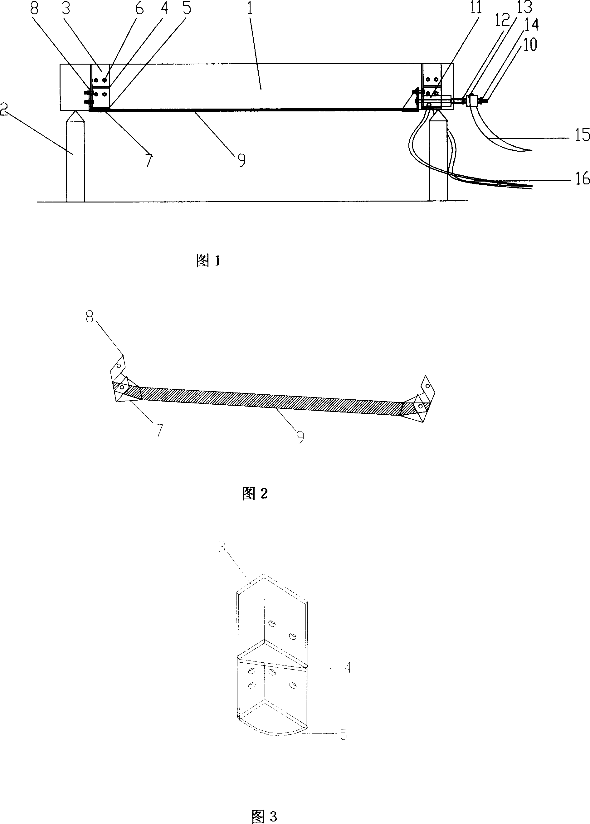
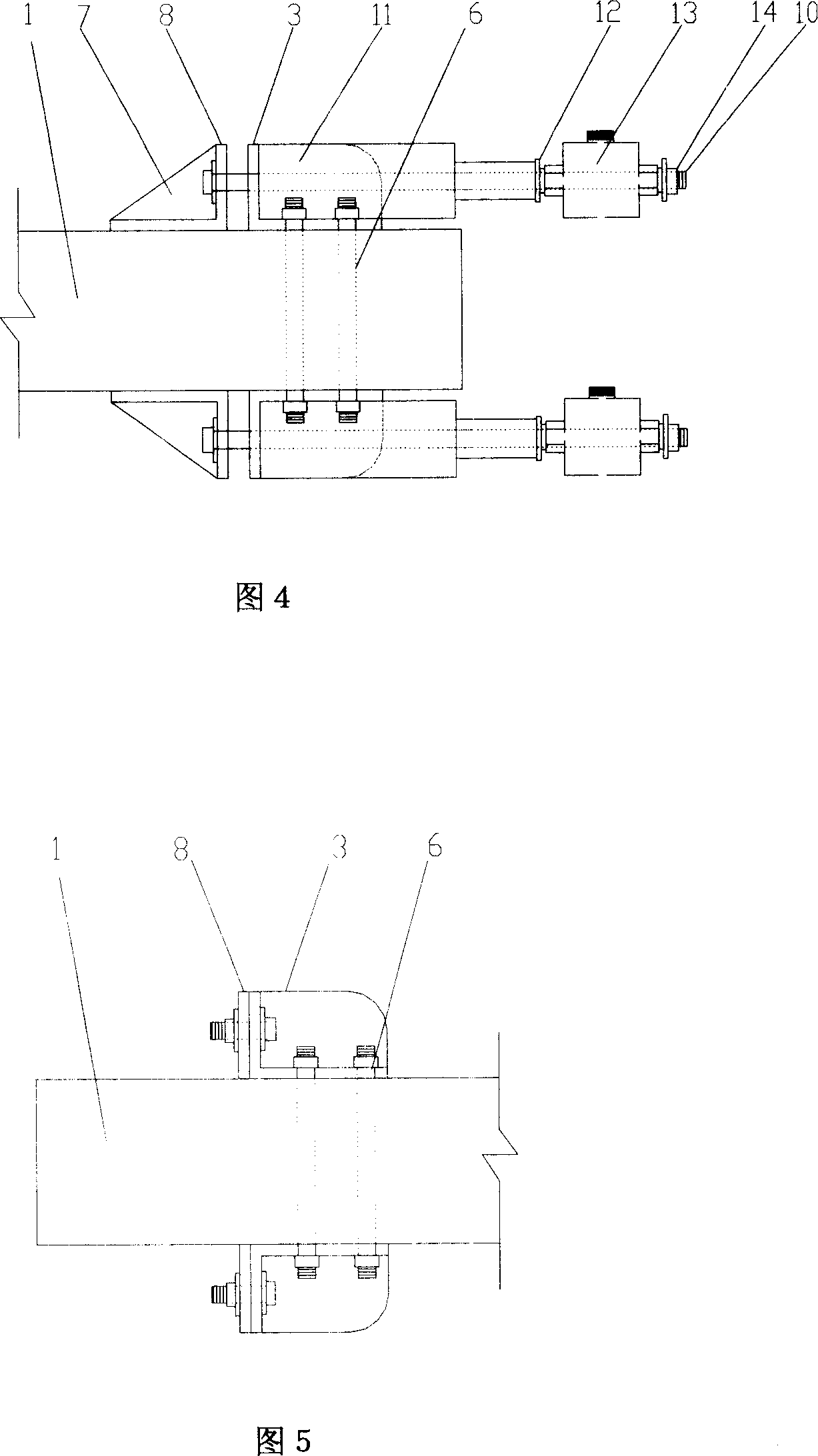
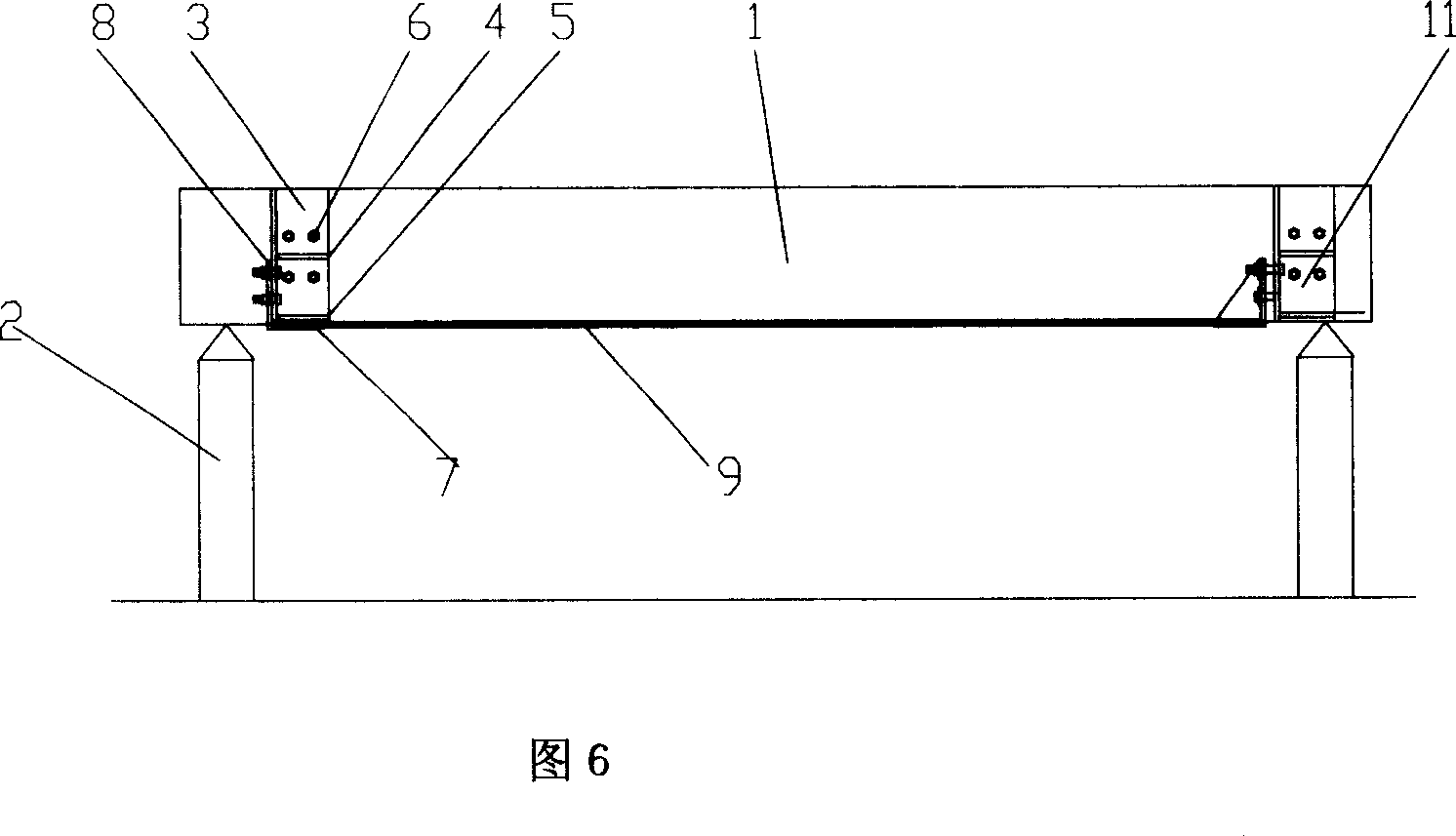
[0019] The two ends of the concrete beam 1 on the bracket 2 are installed in pairs corresponding to the angle steel 3 according to the designed position, and each pair of angle steel uses four bolts 6 to penetrate the beam section, and the middle part of the angle steel has a reinforcing rib 4 and a supporting plate 5 , the distance between the two anchor vertical plates 8 is the same as the width of the concrete beam section, calculate the use length of the CFRP cloth 9, wind the CFRP cloth to the fixed end and the tension end anchor base plate 7 respectively and paste them, and then, polish the concrete At the bottom of the beam, apply primer to the bottom of the beam, install the anchor with CFRP cloth on the beam, the concrete beam 1 is located between the two anchor vertical plates 8, the bottom of the beam is attached to the bottom plate of the anchor, and each of the anchor The vertical plates are fixedly connected with the angle steel 3 with bolts 6 respectively, and at...


PUM


Abstract

The invention relates to a construction technology for strengthening concrete beams with prestretching CFRP, in which fixed angle steel and anchorage device are set on two ends of concrete beams and it is prestretched at one end. There is strengthening ribbed plate in the angle steel and support plate is set at the lower part; one of angle steels is corresponded with another in two angle steels and is fixed with the beam by bolt at two ends of concrete beams. The anchorage device is formed by the bottom plate and two upright plates fixing in vertical direction, between which the interval is set. First of all, base rubber for strengthening is set at the bottom of beam, CFRP fabric is used to wind and paste on base plates of two anchorage devices respectively, concrete beam is set between two upright plates of anchorage devices, each one is fixed with the angle steel. At the end of anchorage device hoisting jack is set on the support plate and the pull-rod, which passes through upright plate of anchorage device, angle steel, hoisting jack, gasket and loading sensor, is fixed with nut. The loading sensor is connected with strain box and the hoisting jack is connected with oil pump and oil pressure sensor. The CFRP fabric is prestretched by oil pressured pump and after that it is fixed. Face glue is used to paint the CFRP fabric again so as to combine the CFRP fabric and concrete beams together.

Description

technical field [0001] The invention relates to a construction technique for reinforcing concrete beams with pre-tensioned carbon fiber cloth, in particular to an anchoring device and a construction method for strengthening concrete beams with pre-tensioned carbon fiber cloth. Background technique [0002] At present, there are many old buildings. Due to the constraints of the economic and technical level at the time of design, the load-bearing strength is low, and the durability and safety are poor. With the increase of the service life and the change of the load, reinforcement is urgently needed to eliminate potential safety hazards. ,Extended service life. Studies have proved that: carbon fiber cloth (CFRP) has the advantages of high strength, small volume and dead weight, no need for welding point connection, and corrosion resistance. The test shows that: when the steel bar yields, the CFRP sheet only exerts less than 20% of its strength. If pre-tension is applied to th...

Claims


Application Information

Patent Timeline
Patent Type & Authority Applications(China)
IPC IPC(8): E04G23/02E04G21/12
Inventor 顾祥林高鹏张伟平李翔
Owner TONGJI UNIV
Why Eureka
Try Eureka