
Manufacturing method of plasma display panel

A technology of a display panel and a manufacturing method, which is applied in the manufacture of discharge tubes/lamps, cold cathodes, tubes/lamp screens, etc., can solve the problems such as the reduction of the light transmittance and internal pressure characteristics of the display panel, and improve the transmittance. and internal pressure characteristics, the effect of preventing air bubbles

Inactive Publication Date: 2007-05-30
LG ELECTRONICS(NANJING) PLASMA CO LTD
View PDF0 Cites 0 Cited by
  • Summary
  • Abstract
  • Description
  • Claims
  • Application Information

AI Technical Summary

Problems solved by technology

[0014] Therefore, even after the charged body layer is formed, the light transmittance and internal pressure characteristics of the display panel will be greatly reduced due to carbon and air bubbles remaining inside the film.

Method used


Image

  • Manufacturing method of plasma display panel
  • Manufacturing method of plasma display panel
  • Manufacturing method of plasma display panel

Examples


Embodiment Construction

[0031] Hereinafter, an embodiment of a method of manufacturing a plasma display panel of the present invention will be described in detail with reference to the drawings.

[0032] In the following description, only the case of the charged layer formed on the upper substrate and the lower substrate will be described, but the case of the pressed charged substance on other plasma display panels is also the same as described here.

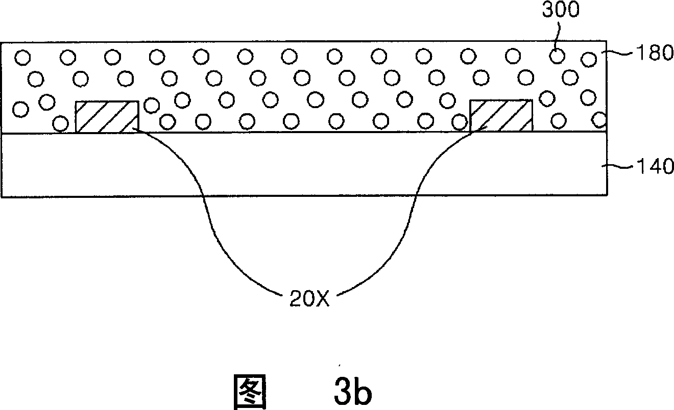
[0033] Shown in FIGS. 3a and 3b are other plasma display panels according to embodiments of the present invention.

[0034] FIG. 3 a illustrates the lower charged layer 180 pressed on the lower substrate 140 of the plasma display panel; FIG. 3 b illustrates the upper charged layer 120 pressed on the upper substrate 160 .

[0035] First, the upper substrate 160 is described: the scan / sustain electrode 40Y and the common sustain electrode 40Z are formed side by side on the upper substrate 160; a mixture of charged substances and oxygen particles (O 2 ) ...


PUM


Abstract

This invention provides one plasma display panel process method, which forms discharge space between top baseboard and down baseboard in the panel and has wall charge electricity layer. The process method comprises the following steps: mixing adhesive agent, solvent, adhesive agent, glass powder, oxidation particle to form electric object; coating the above object onto each baseboard; bursting the electricity object to form electricity layer. This invention can form the electricity layer of the plasma display panel.

Description

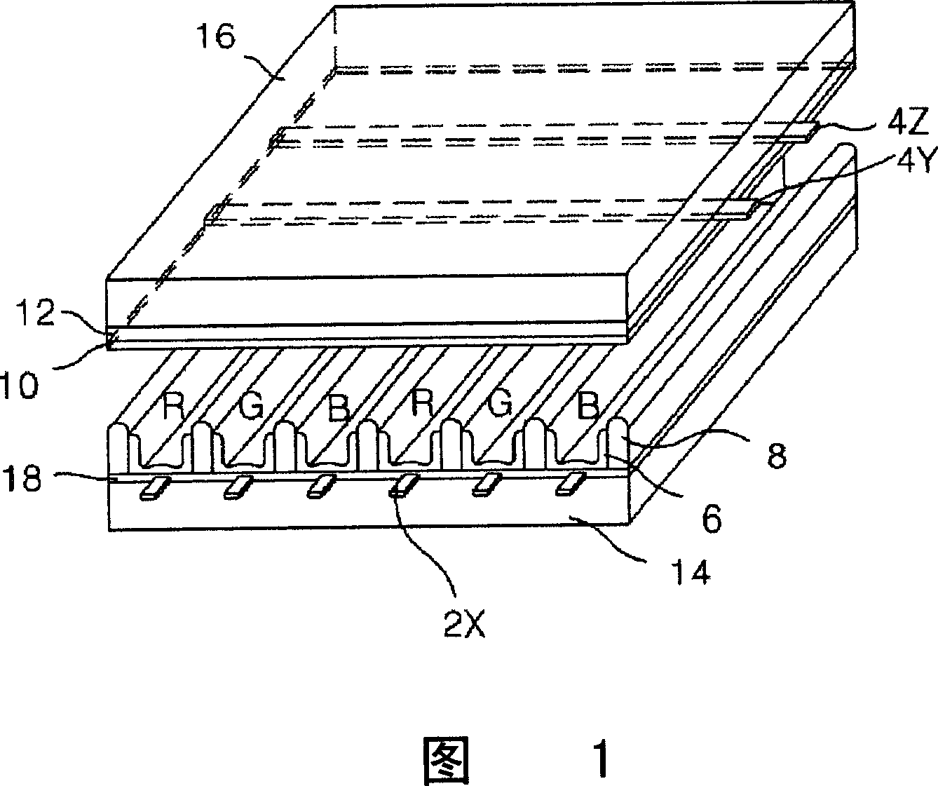
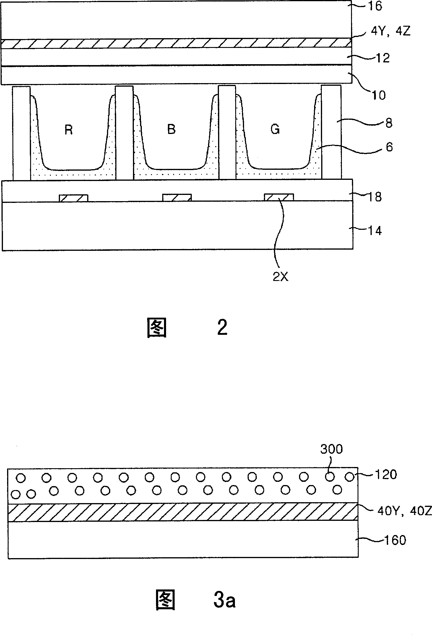
technical field [0001] The present invention relates to the technology of the manufacturing method of the plasma display panel, especially how to prevent carbon elements and bubbles that may remain on the charged body layer after forming the charged body layer, and then improve the light transmittance and internal pressure characteristics of the panel A method of manufacturing a plasma display panel. Background technique [0002] A plasma display panel (Plasma Display Panel: PDP) is a display device using visible light. When the phosphor is excited by vacuum ultraviolet rays generated by gas discharge, visible light is emitted from the phosphor. Plasma display panels use this visible light. [0003] Compared with the cathode ray tube (CRT) display that has been the main display method, PDP has the characteristics of lightness and thinness; and its highly vivid picture quality and large display area are its unique characteristics. . [0004] FIG. 1 is a perspective view o...

Claims


Application Information

Patent Timeline
IPC IPC(8): H01J9/00H01J9/20
Inventor 禹盛浩
Owner LG ELECTRONICS(NANJING) PLASMA CO LTD
Learn More