Optical amplification unit with span loss tilt compensation, fiber optical transmission system comprising the same, and corresponding methods

一种光放大、光放大器的技术,应用在传输系统、电磁波传输系统、激光器等方向,能够解决没有获得补偿效果等问题,达到增益误差减小、系统性能改进、低成本的效果

Inactive Publication Date: 2007-05-30
ALCATEL LUCENT SAS
View PDF1 Cites 3 Cited by
  • Summary
  • Abstract
  • Description
  • Claims
  • Application Information

AI Technical Summary

Problems solved by technology

After 20 optical amplification units and subsequent fiber spans, the cumulative error will be 6dB, which is unacceptable
Tilting the gain of an optical amplifier using e.g. a VOA does not achieve the desired compensation effect since the remaining channels are at the same wavelength

Method used


Image

  • Optical amplification unit with span loss tilt compensation, fiber optical transmission system comprising the same, and corresponding methods
  • Optical amplification unit with span loss tilt compensation, fiber optical transmission system comprising the same, and corresponding methods
  • Optical amplification unit with span loss tilt compensation, fiber optical transmission system comprising the same, and corresponding methods

Examples


Embodiment Construction

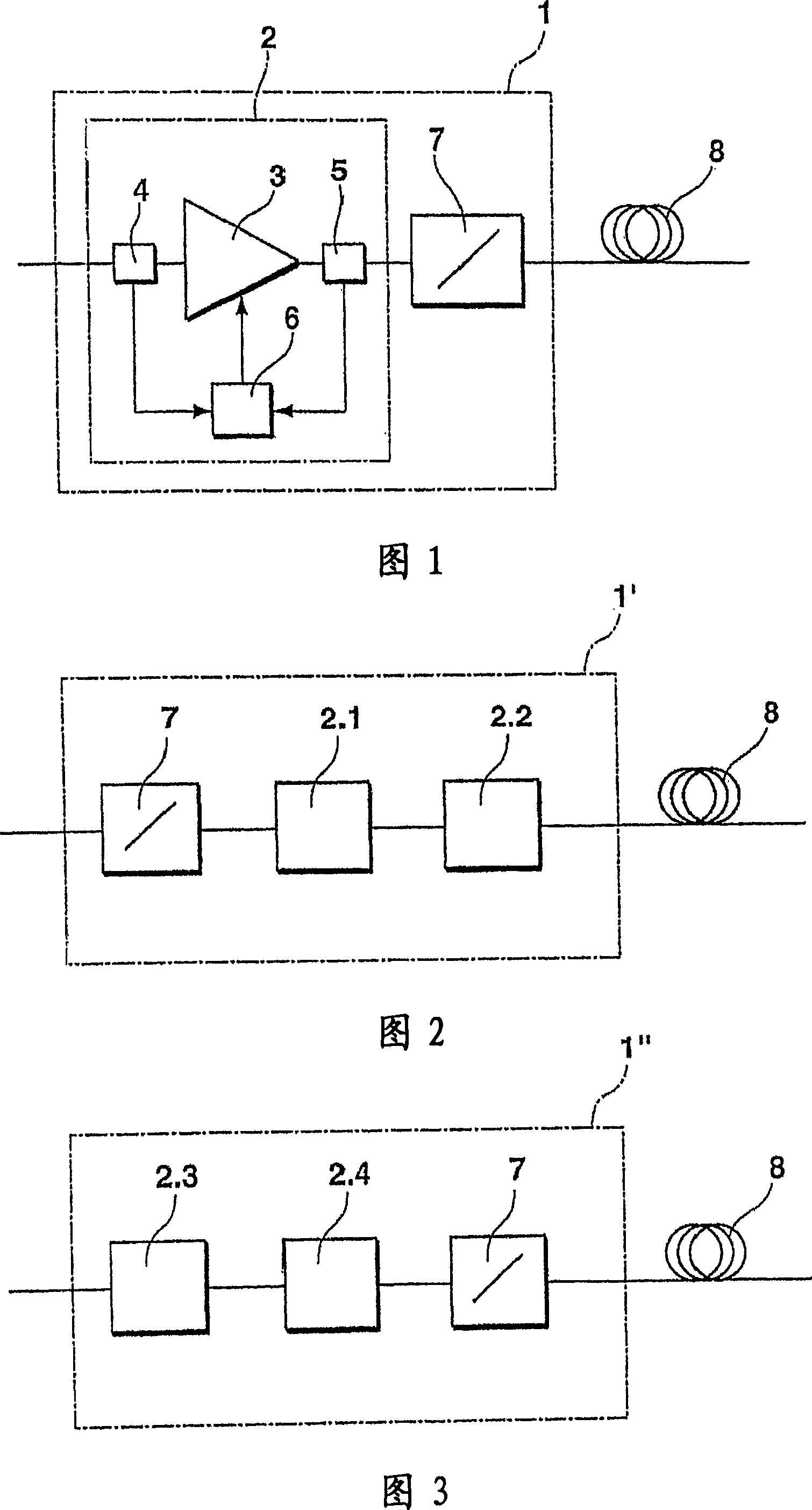
[0030] Fig. 1 shows an optical amplifying unit 1 with an optical amplifier 2, which is an EDFA in this example, and includes an amplifier stage 3 with a gain flattening filter GFF (not shown) for compensating for the non-flat gain of the erb-doped fiber, Input measuring device 4, output measuring device 5, and control circuit 6. The optical amplification unit 1 also includes a filter 7 and can be connected to an optical fiber span 8. The optical amplifying unit shown in FIG. 1 is used in the optical fiber transmission system described in FIG. 5 below.

[0031]The input measurement device 4 and the output measurement device 5 are preferably photodiodes, which measure the input power of the optical amplifier 2 or properties related to the input power of the optical amplifier 2, and the output power of the optical amplifier 2 or the output of the optical amplifier 2, respectively. Power-related properties. By using the properties measured by the input measuring device 4 and the prope...


PUM


Abstract

An optical amplification unit comprises at least one optical amplifier for amplifying an optical signal and a filter preceding or following the optical amplifier. The optical amplifier comprises a first measuring device for measuring a property of an input signal of the optical amplifier, a second measuring device for measuring a property of an output signal of the optical amplifier , and a control circuit for controlling a gain characteristic of the optical amplifier in dependence of said input and output signal properties. The filter exhibits a wavelength-dependent attenuation of the optical signal. The optical amplification unit is connectable to an optical fiber span and the filter is adapted to compensate for a span loss tilt caused by said optical fiber span An optical transmission system with at least one such optical amplification unit and corresponding methods.

Description

[0001] Cross-references to related applications [0002] The present invention is based on European priority application EP 05 292 483.4, the content of which is incorporated herein by reference. Technical field [0003] The present invention relates to an optical amplifying unit, including at least one optical amplifier for amplifying optical signals. The optical amplifier includes: a first measuring device for measuring the properties of the input signal of the optical amplifier; and a second measuring device for Measuring the properties of the output signal of the optical amplifier; and a control circuit for controlling the gain characteristics of the optical amplifier according to the properties of the input signal and the properties of the output signal; the optical amplifying unit further includes a filter. Background technique [0004] The optical amplifying unit is used in, for example, an optical fiber transmission system. Such a system usually includes an optical fiber l...

Claims


Application Information

Patent Timeline
Patent Type & Authority Applications(China)
IPC IPC(8): H04B10/17H04B10/08H04B10/294H04B10/296
CPCH04B10/2941H01S3/1301H04B10/296
Inventor 克里斯蒂安·西莫诺加布里埃尔·沙莱
Owner ALCATEL LUCENT SAS
Why Eureka
Try Eureka