Soldering iron with replaceable tip

A soldering iron tip, soldering iron technology, applied in soldering irons, manufacturing tools, welding positions, etc., can solve the problem of high operating cost of composite heaters

Active Publication Date: 2007-05-30
HAKKO CO LTD
View PDF26 Cites 7 Cited by
  • Summary
  • Abstract
  • Description
  • Claims
  • Application Information

AI Technical Summary

Problems solved by technology

On the downside, the third type of replaceable combined heater assembly is expensive to work because once the tip wears out, the heater and sensor unit must also be replaced

Method used


Image

  • Soldering iron with replaceable tip
  • Soldering iron with replaceable tip
  • Soldering iron with replaceable tip

Examples


Embodiment Construction

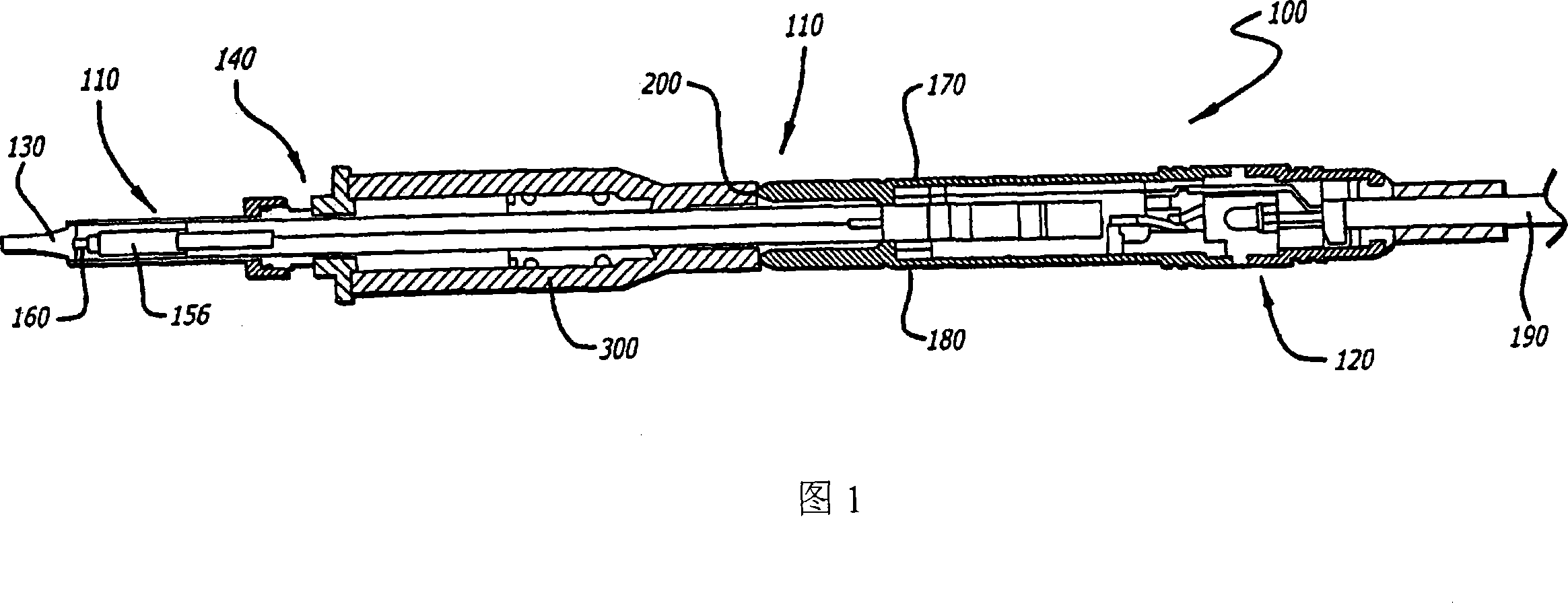
[0073]Referring to FIG. 1 , a soldering iron of the present invention is generally indicated at 100 . The soldering iron 100 includes a heating assembly 110 (or heating unit), shown generally at 110, a connection assembly 120, a replaceable tip cap 130, and a copper or copper alloy 154 removably retaining the tip cap 130 to the heating assembly 110. Retention assembly 140 on conical working head 150 . The heating assembly 110 may also include a heating unit 156 and a temperature sensor 160 . The heating assembly 110 is detachable from the connection assembly 120 for replacement purposes. The heating assembly 110 is snap-fitted to the front end of the connection assembly 120 and retained therein, for example by an O-ring 170 . Soldering iron 100 of FIG. 1 and its structure, components, and operation may perhaps be described from U.S. Patent Application Serial No. 10 / 264,718, filed October 4, 2002, entitled "Soldering Iron Tip and Soldering Iron" (US 2004 / 0065653), and 2002 F...


PUM

PropertyMeasurementUnit
lengthaaaaaaaaaa
diameteraaaaaaaaaa
thicknessaaaaaaaaaa

Abstract

A soldering iron (and a desoldering iron) with a replaceable tip, which is releasably securable on the forward heat-conducting end of a soldering (or desoldering) iron heat assembly. The tip has a tapered heat conducting core in a tip cap. The face of the core can have a depression for mating engagement with a protrusion of the heatconducting end. Also, the face can lie in the rear plane of the tip cap. An assembly which allows for the easy removal and application of a replacement tip can include a sleeve with tightening bolt, a coil spring sleeve, or a slotted compressible sleeve. The tip can thus be replaced after it has worn out, and the heat assembly unit need not be replaced until it has burnt out. Methods of manufacturing and using the tip are also disclosed.

Description

Background of the invention [0001] In the electronics industry, soldering is a method used to join and bond components to provide a strong electrical connection. Welding can be roughly divided into two categories, namely mass welding (batch welding) and manual welding. A lot of soldering is wave soldering or flow soldering, in which electronic components or components are mounted on a printed circuit board and then the printed circuit board is passed over a pool of molten solder in a manner that allows selective contact with the solder. Bulk soldering also includes reflow soldering (SMT), in which solder particles and flux are mixed with binders or additives to form a solder paste. Solder paste is printed on the circuit board, then the electronic components are mounted on the circuit board and heated to solder them. Both methods allow multiple points to be welded simultaneously. [0002] Hand soldering with a soldering iron allows individual operators to perform the solderi...

Claims


Application Information

Patent Timeline
Patent Type & Authority Applications(China)
IPC IPC(8): H05B1/00B23K3/02B22F7/06B22F7/08B23K3/03
CPCB23K3/025B23K3/0369B23K3/0361B22F7/064B22F7/08B22F2998/00B23K3/0338B23K2103/12B22F3/04B22F3/15B22F9/04
Inventor 吉村加代子上谷孝司长濑隆柾木宏之
Owner HAKKO CO LTD
Why Eureka
Try Eureka