Pressure oil box for removing gas in hydraulic oil liquid

A pressurized oil tank and hydraulic oil technology, which is applied in the direction of oil supply tank devices, mechanical equipment, etc., can solve the problems of inability to separate air bubbles, low inlet pressure, hydraulic pump suction, etc., and achieve the effect of speeding up the removal speed and preventing suction

Inactive Publication Date: 2007-06-06
ZHEJIANG UNIV
View PDF0 Cites 15 Cited by
  • Summary
  • Abstract
  • Description
  • Claims
  • Application Information

AI Technical Summary

Problems solved by technology

But this method can not make some tiny air bubbles
In addition, after the fuel tank is evacuated, the inlet pressure o

Method used


Image

  • Pressure oil box for removing gas in hydraulic oil liquid
  • Pressure oil box for removing gas in hydraulic oil liquid
  • Pressure oil box for removing gas in hydraulic oil liquid

Examples


Embodiment Construction

[0020] The present invention will be further illustrated by the accompanying drawings and examples.

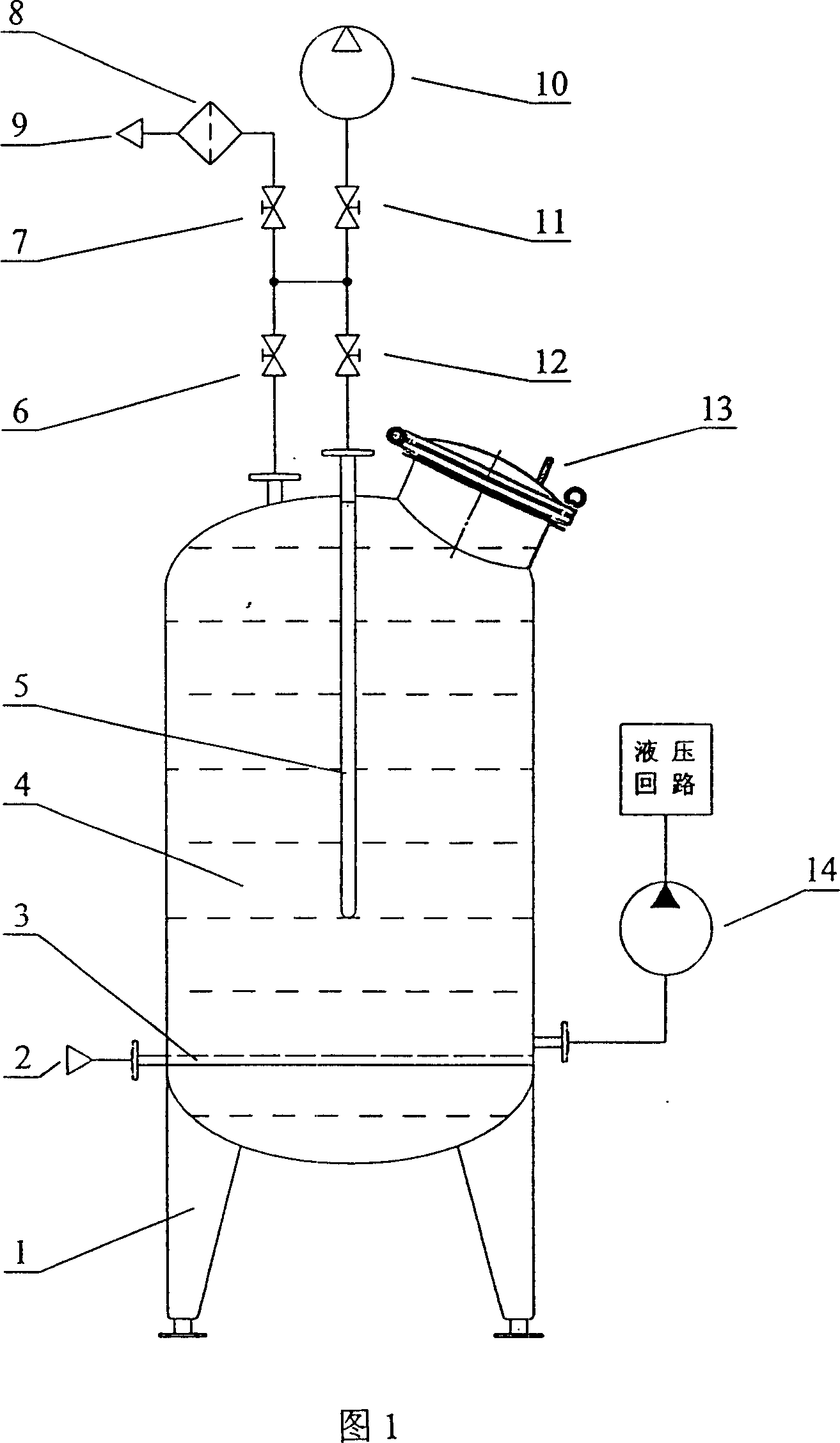
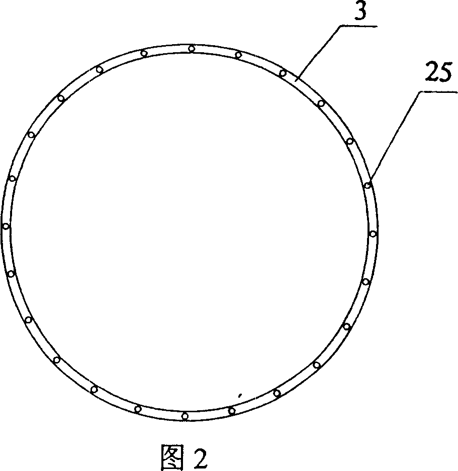
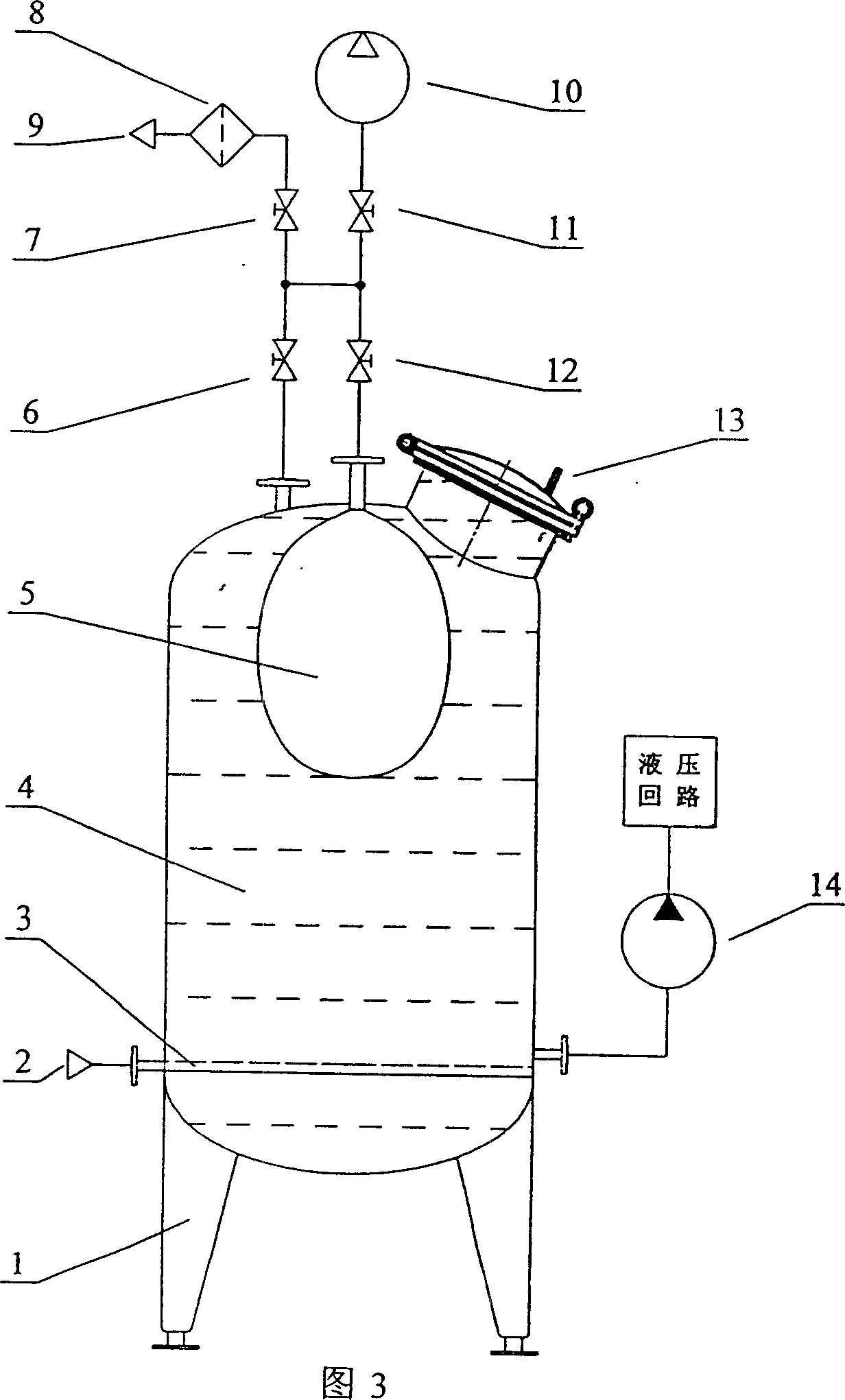
[0021] The first embodiment of the present invention is shown in Fig. 1, Fig. 2, Fig. 3, and the present invention comprises pressure oil tank 4, vacuum device, alternating pressure applying device and the inert gas filling ring that is evenly distributed with exhaust holes 3. The inert gas filling ring 3 is installed at the lower part of the pressure oil tank 4 and connected to the inert gas source 2; the vacuum pump 10 is connected to the top of the pressure oil tank 4 through the first stop valve 11 and the second stop valve 6; alternating The pressure applying device is made up of air bag 5, vacuum pump 10, first shut-off valve 11, the third shut-off valve 12, the fourth shut-off valve 7 and air filter 8, and vacuum pump 10 is connected with the first shut-off valve 11 and the third shut-off valve 12. The air bag 5 installed on the upper part of the pressure oil tank 4 is ...


PUM


Abstract

There is disclosed a pressure oil box capable of removing gas from the hydraulic oil liquid, in which an inert gas filling ring is mounted in the lower part of the pressure oil box and connected with the inert gas source. A vacuum-pumping device is connected with the top of the pressure oil box via a vacuum pump through first and second switch valves. An alternating pressure exerting device consists of a gasbag, a vacuum pump, first, third and fourth switch valves and an air filter. The vacuum pump is connected with the gasbag mounted in the pressure oil box through the first and third switch valves and the air filter is connected with the gasbag mounted in the pressure oil box through the fourth and third switch valves. In the lower part of the pressure oil box is opened an oil mouth connected with the hydraulic pump.

Description

technical field [0001] The invention relates to an oil tank of a hydraulic system, in particular to a pressure oil tank for removing gas in hydraulic oil. Background technique [0002] Under normal temperature and pressure, the amount of air mixed and dissolved in hydraulic oil is about 10%. The elastic modulus of oil dissolved in air is greatly reduced, which weakens the rigidity of the hydraulic system. In components such as hydraulic valves and hydraulic pumps, due to low pressure and strong shear, the dissolved gas in the oil is precipitated to form cavitation, causing cavitation of hydraulic components and generating noise. The presence of air pockets also complicates the flow characteristics of oil. [0003] In order to reduce the gas content of the hydraulic oil, the hydraulic oil tank can be vacuumized to precipitate the dissolved gas in the hydraulic oil. But this method can not make some tiny bubbles precipitate. In addition, after the fuel tank is evacuated, t...

Claims


Application Information

Patent Timeline
IPC IPC(8): F15B1/26
Inventor 杨华勇周城宋伟黄志勇周高明
Owner ZHEJIANG UNIV
Why Eureka
Try Eureka