Semi-closed observing environment for electronic microscope

An electron microscope, semi-closed technology, used in circuits, discharge tubes, measuring devices, etc., can solve the problems of sample flow, unable to penetrate the sample, and the electron beam cannot be smoothly imaged, and achieve the effect of easy observation.

Inactive Publication Date: 2007-06-13
CONTREL TECH CO LTD
View PDF0 Cites 2 Cited by
  • Summary
  • Abstract
  • Description
  • Claims
  • Application Information

AI Technical Summary

Problems solved by technology

However, its disadvantage is that it is impossible to maintain the pressure of the sample chamber close to normal pressure or higher pressure for observation and analysis, because the liquid will evaporate quickly to maintain a stable state of liquid-gas balance, so it must be continuously replenished into the sample chamber. The sample room, but this will cause serious flow of the sample to be observed or uneven mixing of old and new samples, which will affect the authenticity of the observation
In addition, a large amount of volatilized high-pressure steam or high-pressure gas injected into the gas chamber area from the outside will fill the entire space between the upper and lower pole pieces, which will also cause the multiple scattering effect of electrons due to the collision of a large number of gas molecules to become very serious, resulting in the failure of the electron beam Smooth imaging or experiments with electron diffraction
At the same time, the design of the sample chamber cannot effectively control the amount of injected liquid, so it is very easy to cause the thickness of the liquid to be too thick, so that the electron beam cannot penetrate the sample, resulting in the failure of observation and analysis
[0005] At the same time, its design still requires dismantling the main body of the microscope to install these parts, so the possibility of mass production is not high

Method used


Image

  • Semi-closed observing environment for electronic microscope
  • Semi-closed observing environment for electronic microscope
  • Semi-closed observing environment for electronic microscope

Examples


Embodiment Construction

[0039] In order to describe the structure and characteristics of the present invention in detail, the following three preferred embodiments are given below and described in conjunction with the accompanying drawings. Among them, the three embodiments describe that the film is arranged in the observation hole, and the film is arranged in the air hole, and the film is arranged in the air hole. It is set in the state of the outer hole, and it is a semi-closed observation environment.

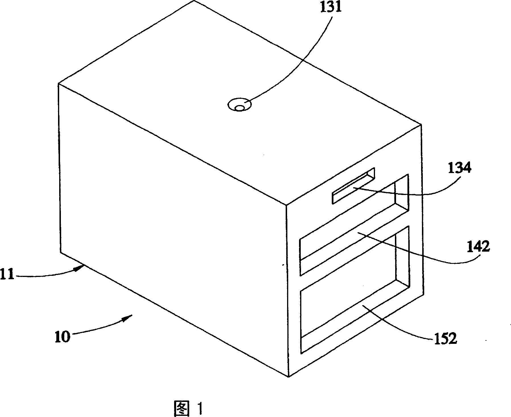
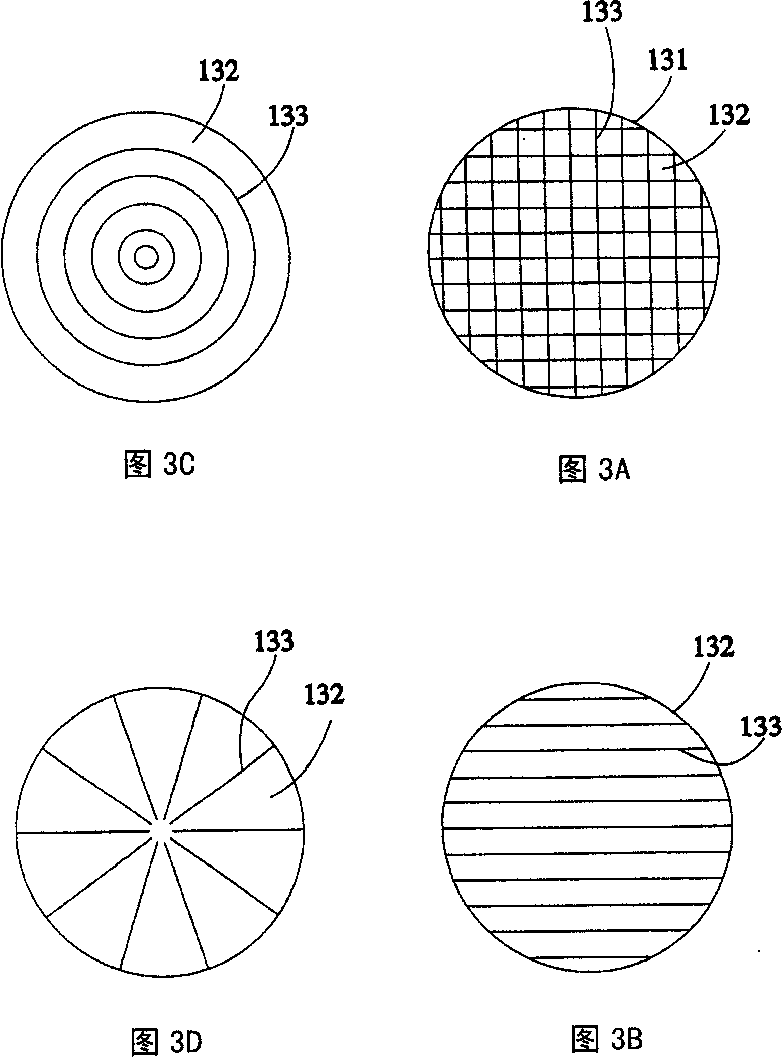
[0040] As shown in Fig. 1 to Fig. 3 (A) figure, the semi-enclosed observation environment 10 that a kind of electron microscope provided by the first preferred embodiment of the present invention mainly has:

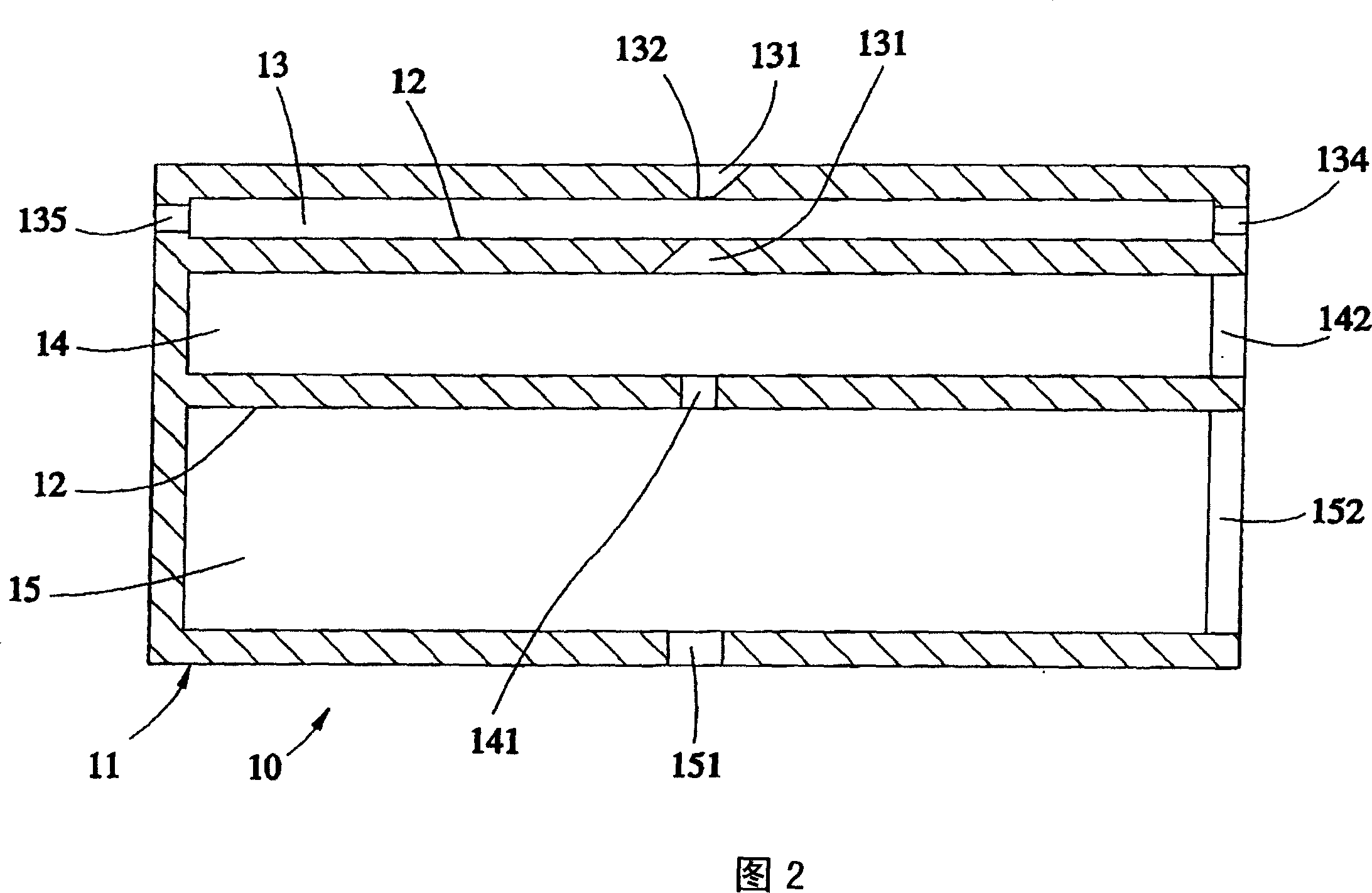
[0041]A housing 11, the interior is separated by at least two partitions 12 to form a chamber 13, and an air chamber 14 below the chamber 13, and a buffer chamber 15 below the air chamber 14, the chamber 13 There is at least one viewing hole 131 on the top surface of the housing 11, and the b...


PUM


Abstract

The invention is for a kind of semiclosed observing circumstance for electron microscope, includes: a covering, the inside is divided into a capacity room by clapboard, and a gas room that is formed under the capacity room, and a buffer room that is formed under the gas room, the top of the capacity room has one observation hole at least that is designed on the covering, the bottom has one observation hole at least that is designed at the clapboard and is connected to the gas room, the bottom of the gas has one air hole at least that is designed another clapboard and is connected to the buffer room, the bottom of the buffer room has one outer hole at least that is designed on the covering and is connected to the outside, the two observation holes, the air hole and the outer hole are at the same axis, and a thin film is set sealed at the observation hole that is at the upper; there is an injection air hole at least that is designed at one side of the gas room for the covering, additionally there is one air bleeding hole at least at one side of the buffer room for the covering, thereout it can provide an observation environment for electron microscope, and with a clear observation result.

Description

technical field [0001] The invention relates to electron microscopes, in particular to a semi-enclosed observation environment for electron microscopes. Background technique [0002] Press, in the known technology, when operating an electron microscope to observe an object, it is usually limited by the vacuum environment of the sample chamber in the electron microscope, so that the object to be observed must be a non-volatile solid to be observed. If it is a volatile object, such as a liquid or gaseous fluid substance, a large amount of gas will be generated after being placed in the vacuum sample chamber, which will not only cause the electron beam to be unable to pass through the object for diffraction or imaging experiments, but also cause the electron gun of the microscope to be high. The vacuum in the vacuum area drops or causes contamination, which damages the electron microscope. [0003] It can be seen from the above that, limited by the limitation of the vacuum env...

Claims


Application Information

Patent Timeline
Patent Type & Authority Applications(China)
IPC IPC(8): H01J37/02H01J37/26G01N13/10
CPCH01J37/20H01J37/26
Inventor 赵治宇谢文俊
Owner CONTREL TECH CO LTD
Why Eureka
Try Eureka