
Laser machining apparatus and its running and controlling methods

A technology of laser processing and laser processing head, which is applied in the direction of laser welding equipment, metal processing equipment, welding equipment, etc., and can solve the problem of extra cost of structure

Inactive Publication Date: 2007-06-20
PRECITEC GMBH
View PDF3 Cites 12 Cited by
  • Summary
  • Abstract
  • Description
  • Claims
  • Application Information

AI Technical Summary

Problems solved by technology

However, this type of monitoring requires the sensor electrodes to be connected to two wires, which in practice entails considerable structural additional effort and is not possible with a certain design of the nozzle body.

Method used


Image

  • Laser machining apparatus and its running and controlling methods
  • Laser machining apparatus and its running and controlling methods
  • Laser machining apparatus and its running and controlling methods

Examples


Embodiment Construction

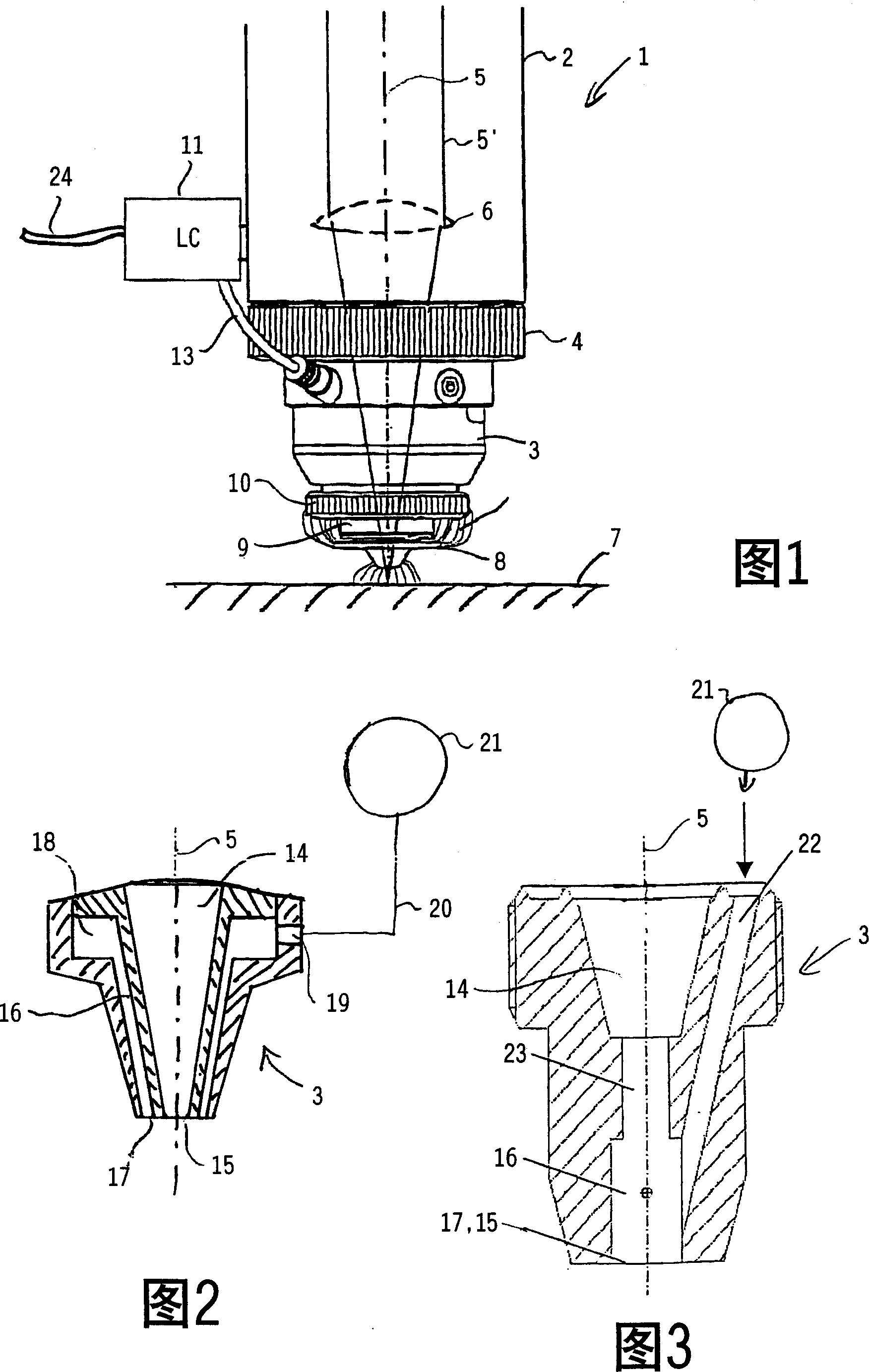
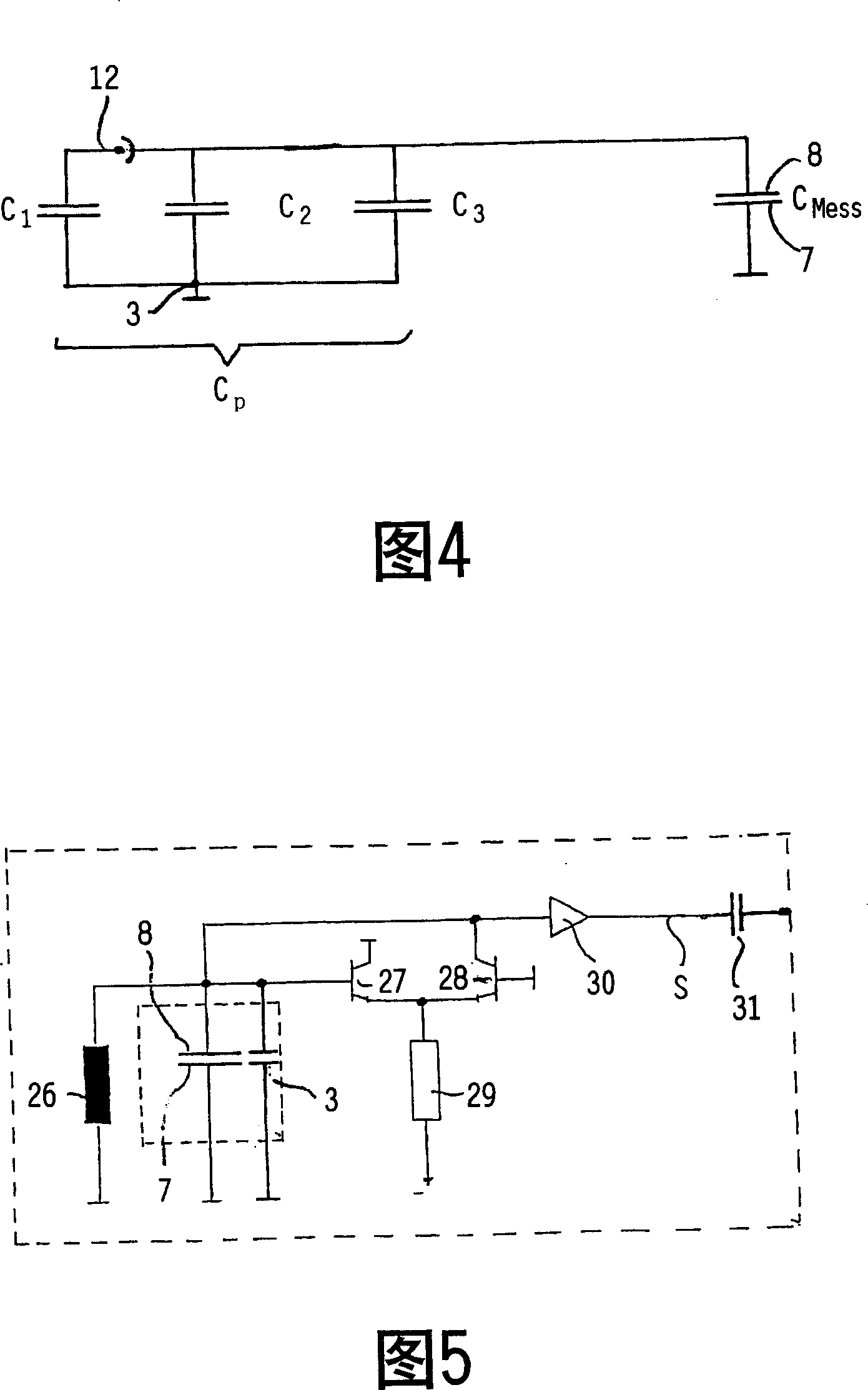
[0045] FIG. 1 shows a laser processing head 1 as used in a laser processing installation according to the invention. The laser machining head 1 has a housing 2 which carries a nozzle 3 at its lower end. The housing 2 and the nozzle 3 can be tightened against one another, eg by means of a knurled screw 4 . A working beam path 5 for a laser beam 5 ′ which is focused by means of a lens arrangement 6 arranged in the housing 2 passes through the housing 2 and the nozzle 3 . The focus of the laser beam 5 ′ lies outside the laser machining head 1 substantially on the surface of the workpiece 7 which is to be machined by means of the focused laser beam 5 ′. Cutting or welding processes and the like can be carried out in this way. Arranged at the lower end of the nozzle body 3 is a sensor electrode 8 made of an electrically conductive material, which is made of an electrically conductive material, in particular metal, for example copper. This sensor electrode 8 is held by a ceramic ...


PUM


Abstract

A laser machining apparatus has a laser machining head, which is composed of a casing, a nozzle with a central channel of laser beam for an emitting outlet and a channel of processing gas, a focusing lens set for focusing the laser beam to a working focus point, a processing gas delivering unit, a sensor electrode for measuring the distance between nozzle and workpiece, and a distance regulator. Its control method is also disclosed.

Description

technical field [0001] The invention relates to a laser processing device with a laser processing head for processing workpieces by means of a laser beam and to a method for operating and controlling such a laser processing device. Background technique [0002] When processing workpieces by means of a laser beam while using processing gases, i.e. shielding gases or cutting gases or the like, the distance between the workpiece and the laser processing head is usually capacitively detected in order to adjust the focus position, in which In the laser processing head there is an optical system, for example a mirror or a lens system for focusing the laser beam. In this technology, a sensor electrode, for example made of a conductive metal, such as copper, can be used as an electrode of a capacitor on the tip of the nozzle body of the nozzle of the laser processing head in order to detect The distance change of the workpiece is used as the capacitance change. Here, the nozzle se...

Claims


Application Information

Patent Timeline
IPC IPC(8): B23K26/00B23K26/14B23K26/04B23K26/42B23K26/70
Inventor 格奥尔格·施珀尔贝尔特·许尔曼
Owner PRECITEC GMBH
Learn More