Transferring apparatus

A transmission device and track technology, applied to storage devices, packaging, conveyors, etc., can solve problems such as multiple vibrations and noises, increased running time, and reduced running speed of the conveying body

Inactive Publication Date: 2007-06-20
SAMSUNG ELECTRONICS CO LTD
View PDF1 Cites 17 Cited by
  • Summary
  • Abstract
  • Description
  • Claims
  • Application Information

AI Technical Summary

Problems solved by technology

[0006] However, in the existing device, when the rollers run on the bifurcated track with a curved portion, more vibration and noise will occur, and other components may be damaged due to impact and other reasons
As a result, the running speed of the conveying body on the branch track will also be significantly reduced, resulting in a large increase in the overall running time

Method used


Image

  • Transferring apparatus
  • Transferring apparatus
  • Transferring apparatus

Examples


Embodiment Construction

[0024] Hereinafter, preferred embodiments of the present invention will be described in detail with reference to the accompanying drawings. Among various transfer devices, an overhead transfer device for transferring a reticle, a front opening unified pod (FOUP: Front Opening Unified Pod) and the like in a semiconductor production process will be exemplified.

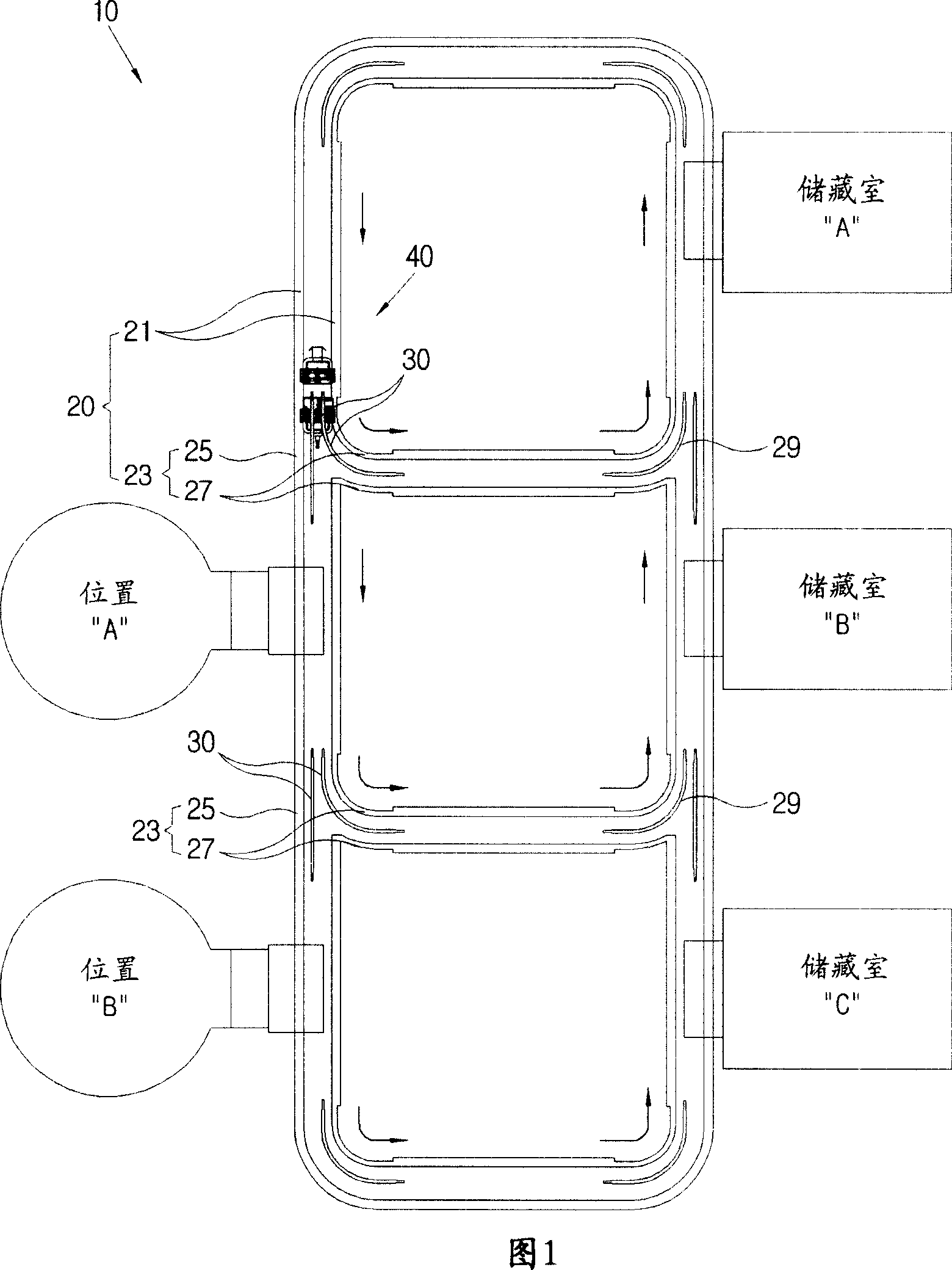
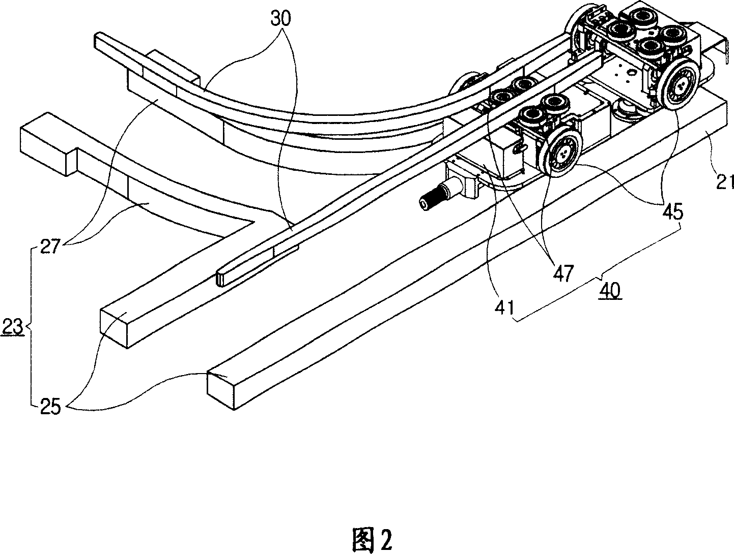
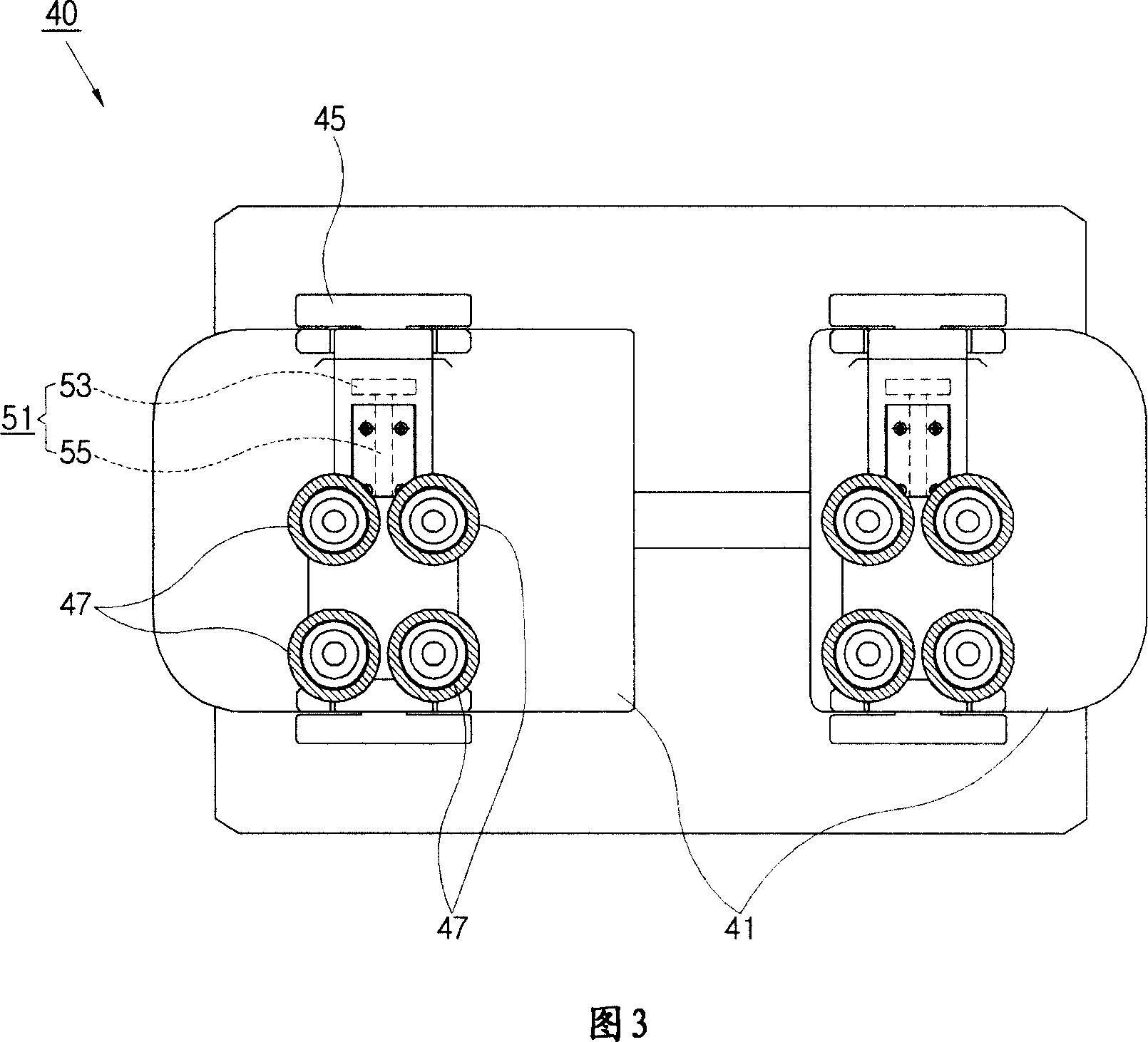
[0025] As shown in Fig. 2 to Fig. 4, conveying device 10 comprises: guide rail 20, and this guide rail 20 has the main track 21 that is formed by a pair of track parts and the branch track 23 that forms from main track 21 branch; The branch area of ​​23 is provided along the auxiliary guide rail 30 of the branch track 23; Side contact guides the guide wheel 47 of the transport vehicle main body 41 to change the running track. The conveying device 10 further includes a control unit 60 for controlling the driving and stopping of the guide wheel moving unit 51 , so that the transport vehicle body 41 can selectively run on...


PUM


Abstract

The invention relates to a transferring apparatus, comprising: a guide rail, having a main rail formed by a pair of rail elements and a branch rail forked form the main rail; an auxiliary guide equiped along the branch rail in a branch range of the branch rail; a van unit having a van body running along the guide, and a guide wheel which couples to the van body, contacts withe both sides of the auxiliary guide, and guides the auxiliary guide to change the running path thereof. Thereby, vibration and noise of the van unit can be reduced in the branch range, and damage, etc., due to shocking can be prevented, while more stably and rapidly transferring the operating objects.

Description

technical field [0001] The invention relates to a conveying device, in particular to a conveying device capable of reducing vibration and noise in a branching area. Background technique [0002] In general, conveyors are used in various fields to convey workpieces, and are classified into various types such as automatic type and overhead type. Next, we will explain a transfer device with an overhead truck unit that automatically transfers a reticle (Reticle) and a wafer transfer pod (FOUP: Front Opening Unified Pod) between processes on a semiconductor production line or from a storage location. Waiting for jobs. The speed of this kind of conveying device directly affects the conveying speed of the work, and then affects the entire process time, so every effort is made to make it possible to convey the work quickly and stably. [0003] Usually, in order to transfer the work between each process, such a conveying device includes: a main rail composed of a pair of rail membe...

Claims


Application Information

Patent Timeline
Patent Type & Authority Applications(China)
IPC IPC(8): B65G35/00H01L21/677
CPCB61B13/00B65G1/026B65G47/61B65G2207/28B65G2207/32E01B7/00E01B25/26H01L21/677
Inventor 张珉九边宰圣金琎其金仁哲李升和金成学
Owner SAMSUNG ELECTRONICS CO LTD
Why Eureka
Try Eureka