Measuring device for simultaneously determining a rotation angle and a displacement position

A technology of measuring device and moving position, applied in the direction of measuring device, electromagnetic measuring device, electric device, etc., can solve the problems of labor-intensive optical sensor, expensive grating-cylinder processing, etc., and achieve the effect of high equipment cost

Active Publication Date: 2007-06-20
ASM ASSEMBLY SYST GMBH & CO
View PDF0 Cites 10 Cited by
  • Summary
  • Abstract
  • Description
  • Claims
  • Application Information

AI Technical Summary

Problems solved by technology

But the machining of such a grating-cylinder is very expensive
In addition, a more complex and equally expensive optical sensor is required to measure the position of the light barrier

Method used


Image

  • Measuring device for simultaneously determining a rotation angle and a displacement position
  • Measuring device for simultaneously determining a rotation angle and a displacement position

Examples


Embodiment Construction

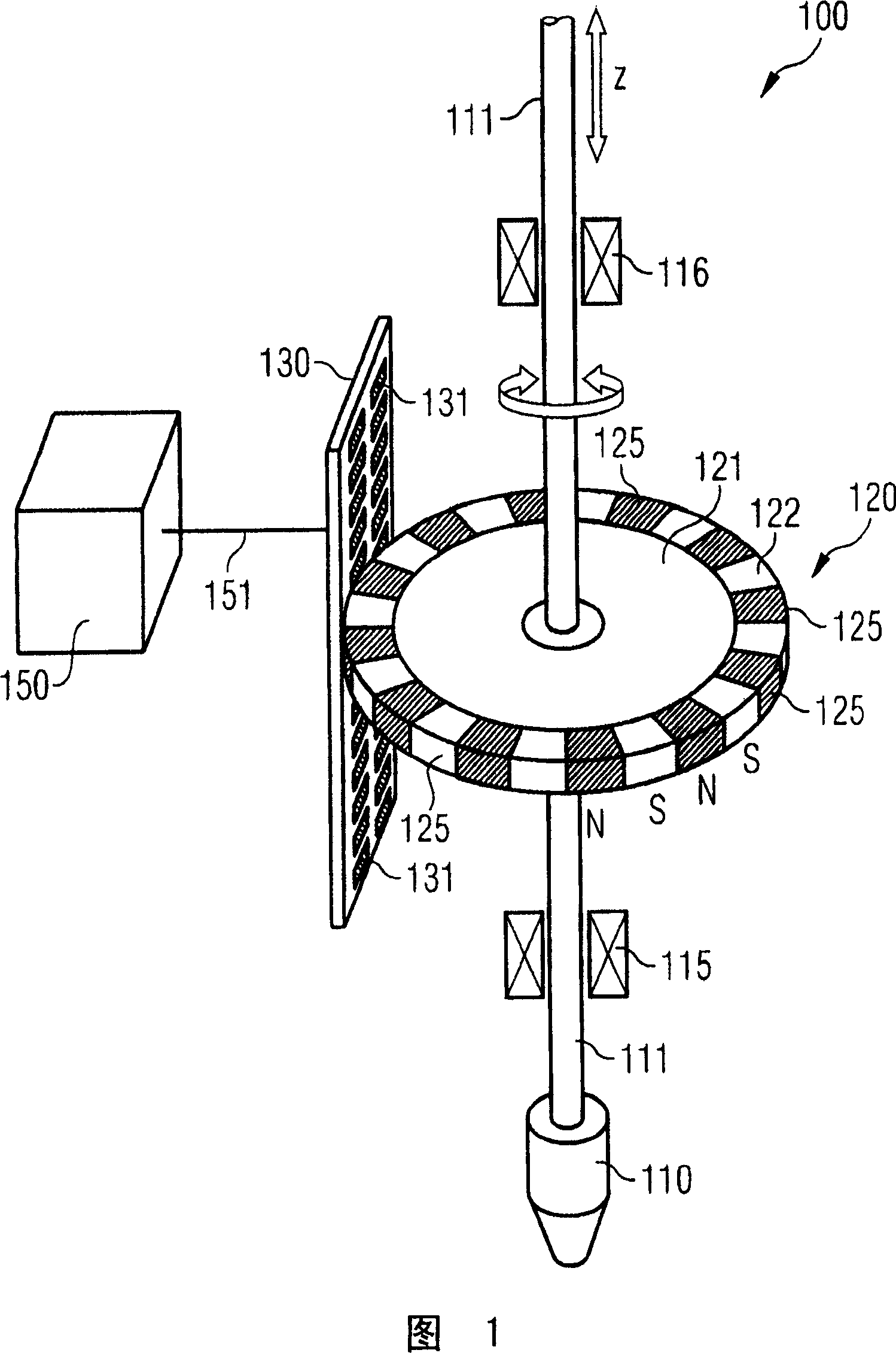
[0032] FIG. 1 shows a measuring device 100 for simultaneously obtaining the angle of rotation and the displacement position of a suction tube 110 as a fixture of a component for carrying out an assembly process. The suction tube 110 rests on a hollow rod 111 , which is a shaft supported by two bearing parts 115 and 116 . The bearing is configured such that the hollow rod 111 is rotatable about its longitudinal axis and also axially displaceable along its longitudinal axis parallel to the z-direction. In a manner not shown, this shaft is coupled not only to a linear drive for axially displacing the hollow rod 111 but also to a rotary drive for rotating the hollow rod 111 about its longitudinal axis. This hollow rod 111 serves to transmit negative pressure to the suction tube 110 from a vacuum generating device not shown, so that elements can be held pneumatically by the suction tube 110 when a corresponding negative pressure is applied.

[0033] The measuring device 100 also i...


PUM


Abstract

The device has a sensor array (130) including individual detectors (131) that are arranged in a level parallel to a swivel pin (111), where the level has a certain distance to an outer edge of a speed sensor (120). An evaluation unit (150) is connected with the detectors and is arranged such that an angle of rotation and a shifting position of an object are determined from a signal of the detectors. A measuring signal of the detectors is measured and evaluated during screwing up of the sensor, where the detectors are arranged next to difference longitudinal sections of the swivel pin.

Description

technical field [0001] The invention relates to a measuring device for simultaneously obtaining an angle of rotation and a position of movement. The invention relates in particular to a measuring device for determining the angle of rotation and displacement position of a holding device for electrical components, which is typically used in assembly technology for conveying electrical components in the form of a so-called suction tube. Background technique [0002] The automatic assembly of electronic components to substrates or circuit boards is currently usually carried out by so-called assembly machines. Here the components are transported by the component transport device via the assembly head to the placement position on the circuit board. The components are received by the device head via a so-called suction tube, which is coupled pneumatically to the vacuum generating unit, so that the components to be assembled can be reliably held by the suction vacuum during transpo...

Claims


Application Information

Patent Timeline
Patent Type & Authority Applications(China)
IPC IPC(8): G01B7/02G01B7/004G01B7/30G01D5/12
CPCH05K13/0413G01D5/145H05K13/0812
Inventor S·伯杰
Owner ASM ASSEMBLY SYST GMBH & CO
Why Eureka
Try Eureka