Planar display device and scanning driver

A technology of scan drive and shift register, used in static indicators, instruments, etc., can solve the problems of wasting components and occupying non-display area space, and achieve the effect of reducing layout complexity

Inactive Publication Date: 2010-05-12
TPO DISPLAY
View PDF5 Cites 0 Cited by
  • Summary
  • Abstract
  • Description
  • Claims
  • Application Information

AI Technical Summary

Problems solved by technology

[0008] However, this architecture requires two shift registers as a pair, and the first shift register has an even number of inverters 204 and 206, and the second shift register has an odd number of inverters. Device 208, when only a single scan line is needed, such as the screen design of mobile phones and personal digital assistants PDA, at this time, part of the components are wasted, or the space of the non-display area is occupied.

Method used


Image

  • Planar display device and scanning driver
  • Planar display device and scanning driver
  • Planar display device and scanning driver

Examples


Embodiment Construction

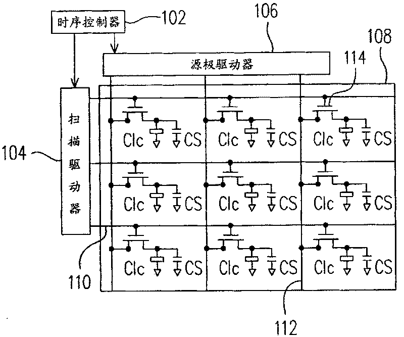
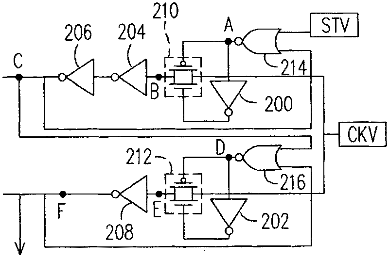
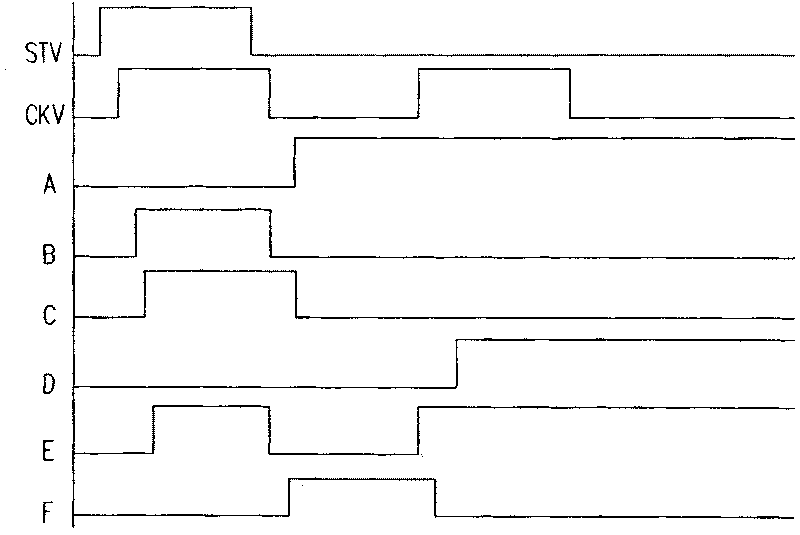
[0047] The internal circuit block diagram of the scan driving device used in one embodiment of the present invention is shown as Figure 4A . In addition, in an embodiment of the present invention, the Figure 4A The flat panel display driven by the scan drive device is shown as Figure 4B. In this embodiment, N shift registers SR_1˜SR_N are included, and each shift register includes an input node node_i, an output node node_o, an inversion logic gate NAND, a switch element SW, and an inversion logic gate INV1 , INV2 and INV3. Among them, the start signal STV is input to the shift register SR1, the odd-numbered shift registers (such as SR1, SR3) receive the scan signal CKV, and the even-numbered shift registers (such as SR2, SR4) The inverse signal of the scanning signal CKV is received.

[0048] Figure 4B The flat panel display used in this embodiment is a liquid crystal display panel as an example. Figure 4B Among them, the scanning drive device 40 is Figure 4A de...


PUM


Abstract

A scan driving device with N numbers of displacement working-storage is prepared as coupling the first input end of inverse-OR gate to input not and it's the second input end to output node, using switch-element to receive output signal of inverse-OR gate to decide whether to connect trough circuit between two said ends or not, coupling input end of the first reversed phase logic gate to the second end and its output end to output node, using the first input node to receive initial signal and odd first end to receive scan signal as well as even first end to receive reversed phase signal of scan signal.

Description

technical field [0001] The present invention relates to a driving device, and in particular to a scanning driving device. Background technique [0002] Liquid crystal displays are widely used in various electronic products such as mobile phones, notebook computers, digital personal assistants (PDAs), digital cameras, and digital video cameras due to their advantages of lightness, thinness, power saving, no radiation, and low electromagnetic interference. Coupled with the industry's active investment in research and development, the quality of liquid crystal displays has been continuously improved. [0003] figure 1 To know the circuit of the liquid crystal display, please refer to figure 1 , which includes a timing controller 102 , a scan driver 104 , a source driver 106 and a liquid crystal panel 108 . The liquid crystal panel 108 further includes a plurality of gate lines 110 for transmitting scanning signals, source lines 112 for transmitting image signals, and a pixel...

Claims


Application Information

Patent Timeline
Patent Type & Authority Patents(China)
IPC IPC(8): G09G3/36G09G3/20G02F1/133
Inventor 罗平
Owner TPO DISPLAY
Why Eureka
Try Eureka