Time-delay locking loop circuit

A technology of delay locked loop and locked loop, applied in the direction of electrical components, automatic power control, etc., can solve the problems affecting the response characteristics and indicators of the system, and achieve the effect of improving the fast response characteristics, suppressing the impact, and shortening the response time.

Active Publication Date: 2011-06-01
SHANGHAI HUAHONG GRACE SEMICON MFG CORP
View PDF3 Cites 0 Cited by
  • Summary
  • Abstract
  • Description
  • Claims
  • Application Information

AI Technical Summary

Problems solved by technology

However, since the DLL uses a voltage-controlled delay line, the delay for DLL locking must be a clock cycle. In order to avoid locking a non-1-cycle clock, the DLL needs to use complex control logic circuits to determine whether the lock is correct, which will Affects the response characteristics and metrics of the system

Method used


Image

  • Time-delay locking loop circuit
  • Time-delay locking loop circuit
  • Time-delay locking loop circuit

Examples


Embodiment Construction

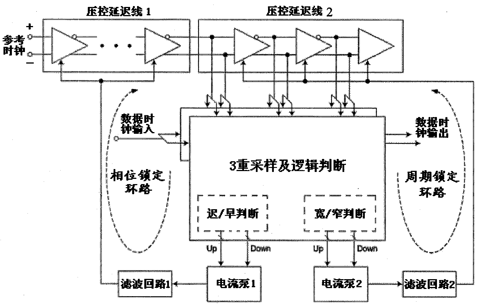
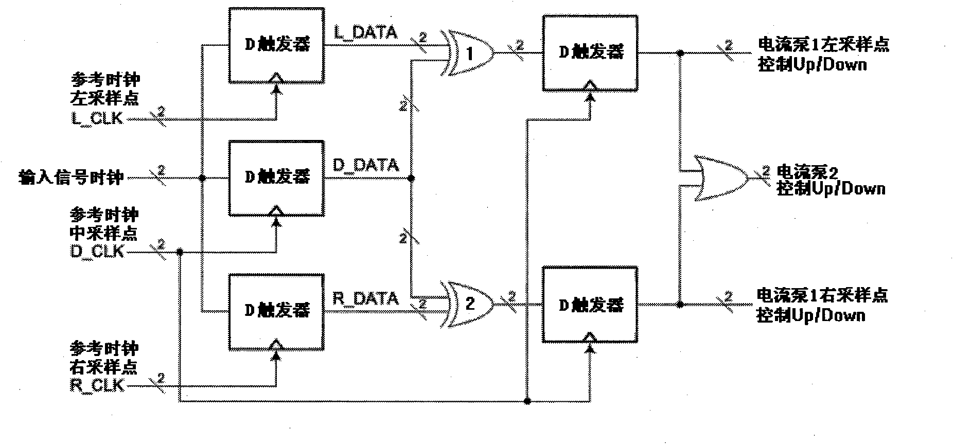
[0020] like image 3 As shown, it is a fully differential double-loop delay locked loop circuit of the present invention. It includes a signal phase-locked loop and a signal period-locked loop connected in series. In the signal path shown in the figure, the signal phase-locked loop includes triple signal sampling and logic judgment circuit, current pump 1, filter circuit 1 and voltage-controlled delay line circuit 1. The signal phase-locked loop first samples the signal through the triple sampling and logic judgment circuit, and judges whether the triple sampling point is in the same clock cycle, if the triple sampling point is not in the same signal clock, through the sooner or later logic ( Early / Late) circuit judges, generates UP / DOWN signals of the left and right sampling points to control the output voltage of the current pump 1, and changes the voltage-controlled delay line 1 through the filter circuit 1, so that the 3 re-sampling points return to the same clock.

[00...


PUM


Abstract

The invention is concerned with the delay time locking loop circuit, it is higher logical control accuracy and faster response characteristic, and restrains the effect leading by the power fluctuation and the molestation from the transmission line. It is: inserts the independent double-loop (the signal phase locking loop and the signal cycle locking loop) sample loop structure in the signal path,uses the ternary signal sample method to process phase (the earlier or later logical judgment) sample / text and signal cycle (the narrow or width logic judgment) sample / text for the clock / data signal,changes the phase and space between the ternary sample points by the voltage controlling delay line if the judgment exists deviation, processes sample of the signal phase and cycle again until lock the signal phase and cycle finally.

Description

technical field [0001] The invention relates to a signal sampling circuit, in particular to a delay locked loop circuit. Background technique [0002] In many microelectronic applications, especially high-speed communication systems, signal quality increasingly depends on the performance of the clock system. Phase-locked loop PLL and delay-locked loop DLL can meet the low phase drift characteristics or low phase error requirements of the system, and are widely used in FM demodulation in communication systems, frequency synthesis of digital communication, and carrier recovery under low signal-to-noise ratio etc. [0003] Basic components of phase-locked loop PLL: phase detector PD, loop filter LPF and voltage-controlled oscillator VCO; such as figure 1 shown. By comparing the phase difference between the input signal and the output signal of the voltage-controlled oscillator, an error control voltage is generated to adjust the frequency of the voltage-controlled oscillator...

Claims


Application Information

Patent Timeline
Patent Type & Authority Patents(China)
IPC IPC(8): H03L7/00H03L7/06
Inventor 晏颖
Owner SHANGHAI HUAHONG GRACE SEMICON MFG CORP
Why Eureka
Try Eureka