
Optical fiber and its preform as well as method and apparatus for fabricating them

An optical fiber preform and preform technology, applied in the field of optical fibers, can solve the problems of disturbing the periodic structure, leaving gaps and openings, etc., to achieve the effect of avoiding labor intensity and cost

Inactive Publication Date: 2007-06-20
SIRITEK FIBER OPTIC CO LTD
View PDF9 Cites 6 Cited by
  • Summary
  • Abstract
  • Description
  • Claims
  • Application Information

AI Technical Summary

Problems solved by technology

However, considering the complex structure of mechanical vibrations, thin capillaries involve the danger of cracking the tube, leaving void openings or disturbing the periodic structure.

Method used


Image

  • Optical fiber and its preform as well as method and apparatus for fabricating them
  • Optical fiber and its preform as well as method and apparatus for fabricating them
  • Optical fiber and its preform as well as method and apparatus for fabricating them

Examples


Embodiment Construction

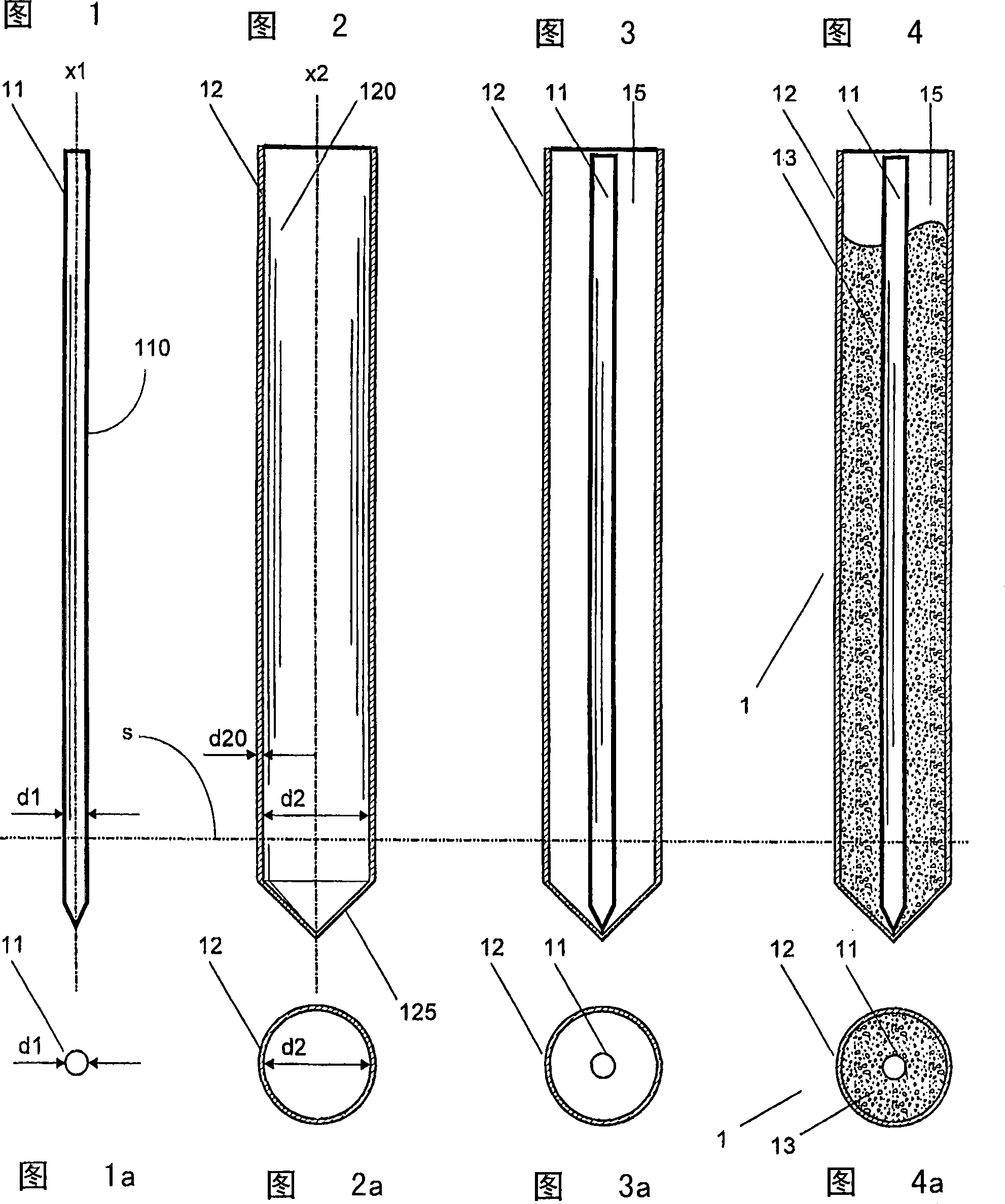
[0093] FIG. 1 shows a primary preform 11 with a first main axis x1 , an outer diameter d1 and an outer surface 111 . The manufacture of such a preform has already been described above.

[0094] FIG. 2 shows a thin-walled silica tube 12 having a first major axis x2 , an inner diameter d2 , an outer diameter d20 and an inner surface 120 . A thin-walled silica tube 12 comprising a conical shell 125 at its lower end is used as overcladding tube 12 according to the method of the invention. Such silica tubes are available from a number of manufacturers.

[0095] Figure 3 shows the primary preform 11 secured in a centrally inserted position within an overcladding tube 12, wherein said first and second main axes x1, x2 are substantially aligned with each other.

[0096] The diameter d20 of the circular wall of the outer cladding tube 12 is, for example, 10 times smaller than its inner diameter d2. However, the ratio of diameter d2 / d20 can be as high as 50 or more. The ratio d2 / d1 ...


PUM

PropertyMeasurementUnit
diameteraaaaaaaaaa

Abstract

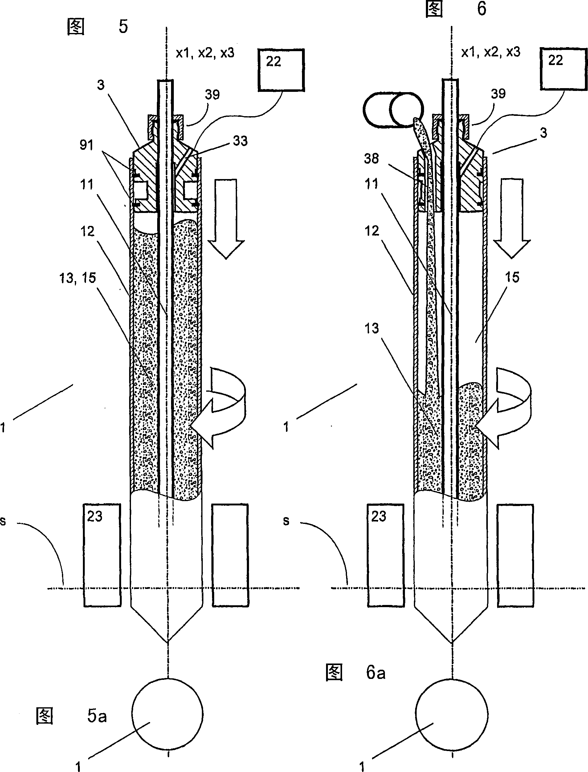
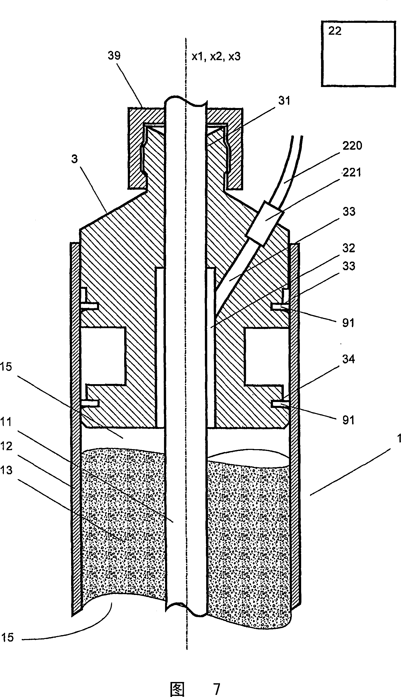
The method for fabricating an optical fiber comprises the steps of inserting a primary optical fiber preform (11) having a first primary axis (x1) and an outer surface (111) into an overcladding tube (12) having a second primary axis (x2) and an inner surface (120), so that said outer surface and inner surface define an interior space (15) ; holding the primary preform (11) in a centrally inserted position within the overcladding tube (12) with said first and second primary axes (x1, x2) in substantial alignment with each other; supplying overcladding grain (13) into the interior space (15) that is limited at the lower end of the overcladding tube (12) by means of a closure (125); generating a condition of reduced pressure within the interior space (15) that is limited at the upper end of the overcladding tube (12) by means of an adjoiner (3), which holds the primary optical fiber preform (11) and the overcladding tube (12) in position; and heating the unprocessed secondary preform (1), that consists of the primary preform (11), the overcladding tube (12) and the overcladding grain (13), at its lower end to a softened state and simultaneously or subsequently drawing an optical fiber therefrom.

Description

technical field [0001] The present invention relates to methods and apparatus for manufacturing optical fibers, such as photonic crystal fibres, and also to preforms for manufacturing optical fibers and to optical fibers manufactured according to said methods. Background technique [0002] The manufacture of optical fibers such as those currently used in ultra-high-speed data communication networks is described in [1], Mool C. Gupta, Handbook of PHOTONICS, CRCPress, 1997 Boca Raton, Chapter 10.7, pp. 445-449. The main procedural steps of optical fiber manufacturing are: making a glass blank (referred to below as a preform), drawing the fiber from the preform, and coating the fiber with a coating to protect the fiber from handling and from environmental influences. Material. [0003] According to literature [1], there are basically three methods of forming preforms, namely, modified chemical vapor deposition (MCVD), external vapor deposition (OVD), and axial vapor deposition...

Claims


Application Information

Patent Timeline
Patent Type & Authority Applications(China)
IPC IPC(8): C03B37/012C03B37/027
CPCC03B37/02754C03B37/01211C03B2205/13C03B37/02736C03B2205/08Y02P40/57G02B6/00C03B37/012
Inventor C·帕德里多
Owner SIRITEK FIBER OPTIC CO LTD
Learn More