Catalytic cracker with external tubular settler

A catalytic cracking unit and settler technology, which is applied in catalytic cracking, cracking, petroleum industry, etc., can solve the problem of rapid separation of oil and gas from catalysts, rapid extraction of oil and gas, affecting the long-term operation of catalytic cracking units, and unplanned shutdown of catalytic cracking units and other problems, to achieve the effect of eliminating coking coke retention, avoiding excessive contact time, and eliminating oil and gas retention space

Inactive Publication Date: 2007-06-27
CHINA UNIV OF PETROLEUM (BEIJING)
View PDF15 Cites 12 Cited by
  • Summary
  • Abstract
  • Description
  • Claims
  • Application Information

AI Technical Summary

Problems solved by technology

Chinese patent CN02159408.2 (2005) discloses a cyclone type quick separator with a splitter cylinder, but the separation efficiency of the swirl arm type quick separator is generally lower than that of the cyclone separator, and the structure is also more complicated than the cyclone separator
Serious coking problems have occurred in heavy oil catalytic cracking units in many refineries, resulting in unplanned shutdown of catalytic cracking units, which directly affects the long-term operation of catalytic cracking units
[0014] Therefore, the existence of a large space inside the settler makes it difficult to realize the rapid separation of oil and gas and catalyst and the rapid extraction of oil and gas, so it is very necessary to reduce the unnecessary space in the settler and the supporting rapid separation equipment for oil and gas and catalyst of
[0015] At present, the development of rapid separation technology for oil and gas and catalyst, and the development of rapid extraction technology for oil and gas are all carried out on the premise of retaining the traditional settler, that is, all the gas-solid rapid separation devices at the outlet of the riser, and the top rotation is set in the settler. In the accommodated space, the space of the settler is very large, the size of the settler is difficult to reduce, and there is a large space for oil and gas retention inside, so it is difficult to ensure the rapid extraction of oil and gas

Method used


Image

  • Catalytic cracker with external tubular settler
  • Catalytic cracker with external tubular settler
  • Catalytic cracker with external tubular settler

Examples


Embodiment Construction

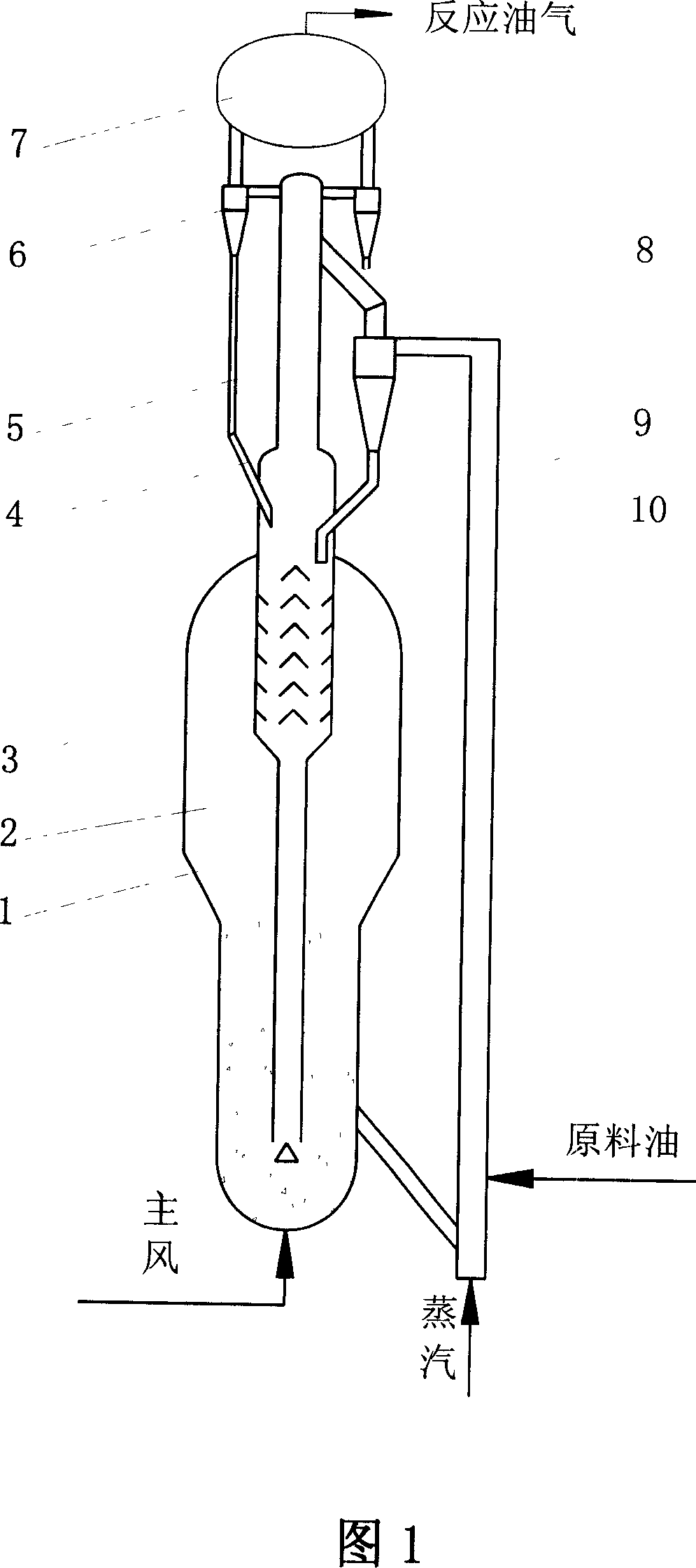
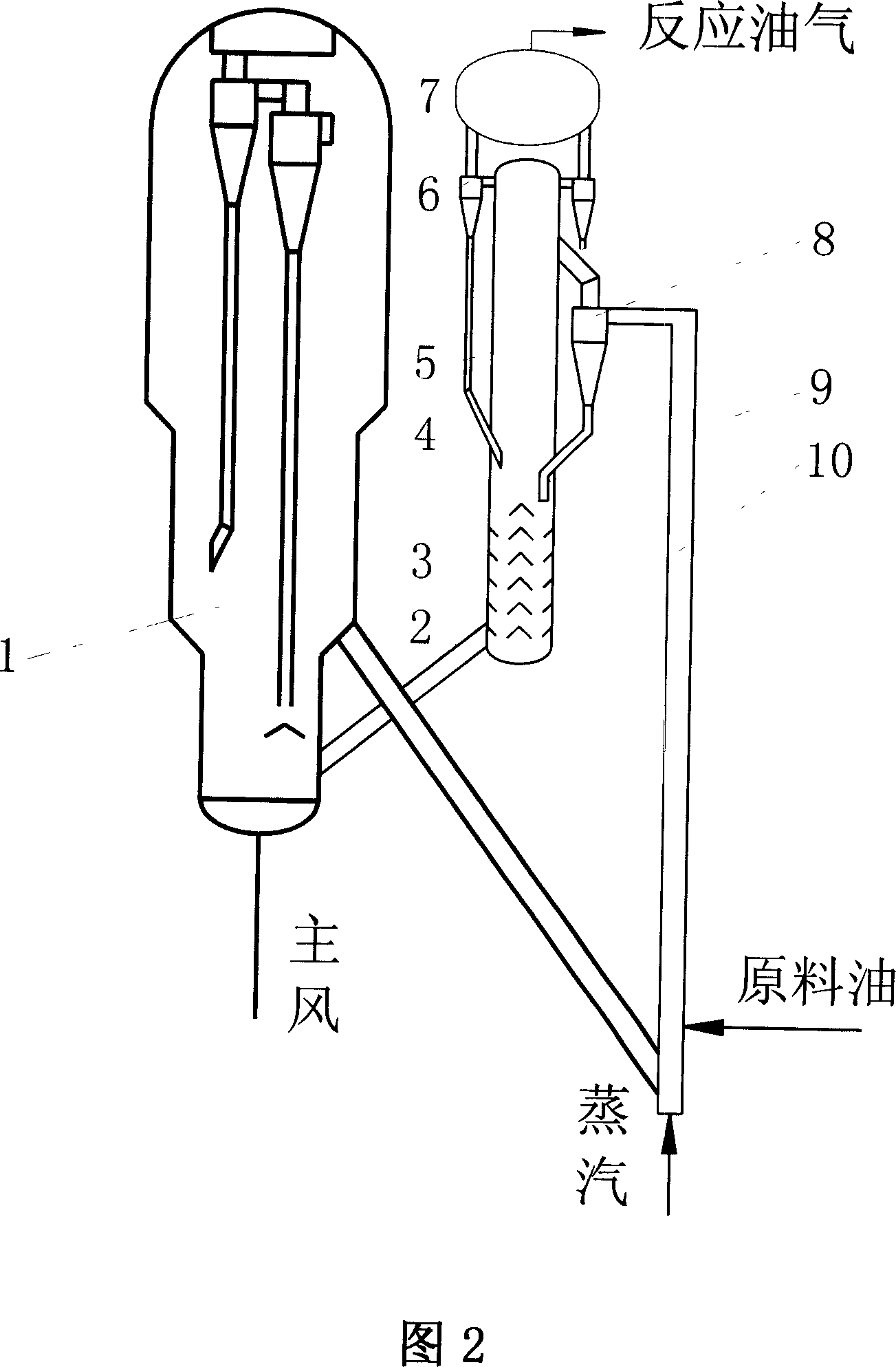
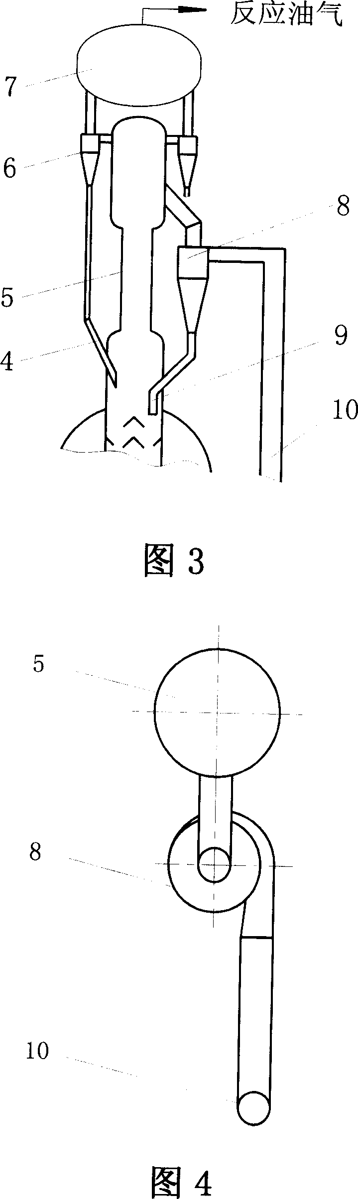
[0045] When using the fluidized catalytic cracking device of the present invention with a rough rotary external tube-type settler, the raw oil and the re-refined oil enter the riser 10 and mix with the regenerated catalyst from the regenerator. Under the action of upward mixing flow, catalytic cracking reaction occurs at the same time. The reaction oil gas and catalyst enter the coarse rotary 8 at the outlet of the riser 10 for primary separation, and the separated oil gas enters the upper part of the tubular settler 5 through the gas outlet pipe of the rough rotary 8, and the oil gas and steam stripped from the stripper Merge and carry a small amount of unseparated fine catalyst particles into the top spin 6 for secondary separation. The oil and gas separated by the top spin 6 will flow into the gas collection chamber 7 and be quickly drawn out by the oil and gas pipeline to the fractionation tower, where it will be separated by the rough spin 8 The catalyst and the catalyst ...


PUM


Abstract

The present invention is fluid catalytic cracker with fast separation of oil gas from catalyst. The fluid catalytic cracker has a riser with outlet connected to thick coiled pipe inside the tube settler, a stripping device below the tube settler, a catalyst regenerator connected through pipe tot lower end of the stripping device, and a top coiled pipe outside the tube settler. The fluid catalytic cracker can realize the efficient and fast gas-solid separation in the separation efficiency as high as 99.99 %, reduce average oil gas residence time to less than 2-3 sec and decrease scaling, and has compact structure and low cost.

Description

technical field [0001] The invention belongs to the technical field of petrochemical industry, and relates to an oil refining and chemical process and equipment thereof, in particular to a rapid separation process of oil gas and catalyst and a rapid extraction process of oil gas in the fluidized catalytic cracking process. Background technique [0002] The fluid catalytic cracking process is one of the important oil lightening processes in the oil refining industry. The catalytic cracking process mainly includes a reaction system, a regeneration system, a fractionation system, and an absorption stabilization system downstream of the fractionation system. The reaction system and regeneration system of the fluidized catalytic cracking unit are its core, and the main equipment includes riser reactor, settler, regenerator, etc. In the catalytic cracking process, the riser reactor is the main place for catalytic cracking of raw oil and gas, and the mixture of catalyst and raw oi...

Claims


Application Information

Patent Timeline
Patent Type & Authority Applications(China)
IPC IPC(8): C10G11/18
Inventor 宋健斐魏耀东卢春喜张锴张静时铭显
Owner CHINA UNIV OF PETROLEUM (BEIJING)
Why Eureka
Try Eureka