Optical inspection method and optical inspection apparatus used for the same
An optical inspection and light source technology, applied in the field of optical inspection, can solve the problems that the measurement results are easily affected by the ambient temperature, and it is difficult to apply optical inspection machines, etc., and achieve the effect of less environmental temperature influence
- Summary
- Abstract
- Description
- Claims
- Application Information
AI Technical Summary
Problems solved by technology
Method used
Image

Examples
no. 1 Embodiment approach
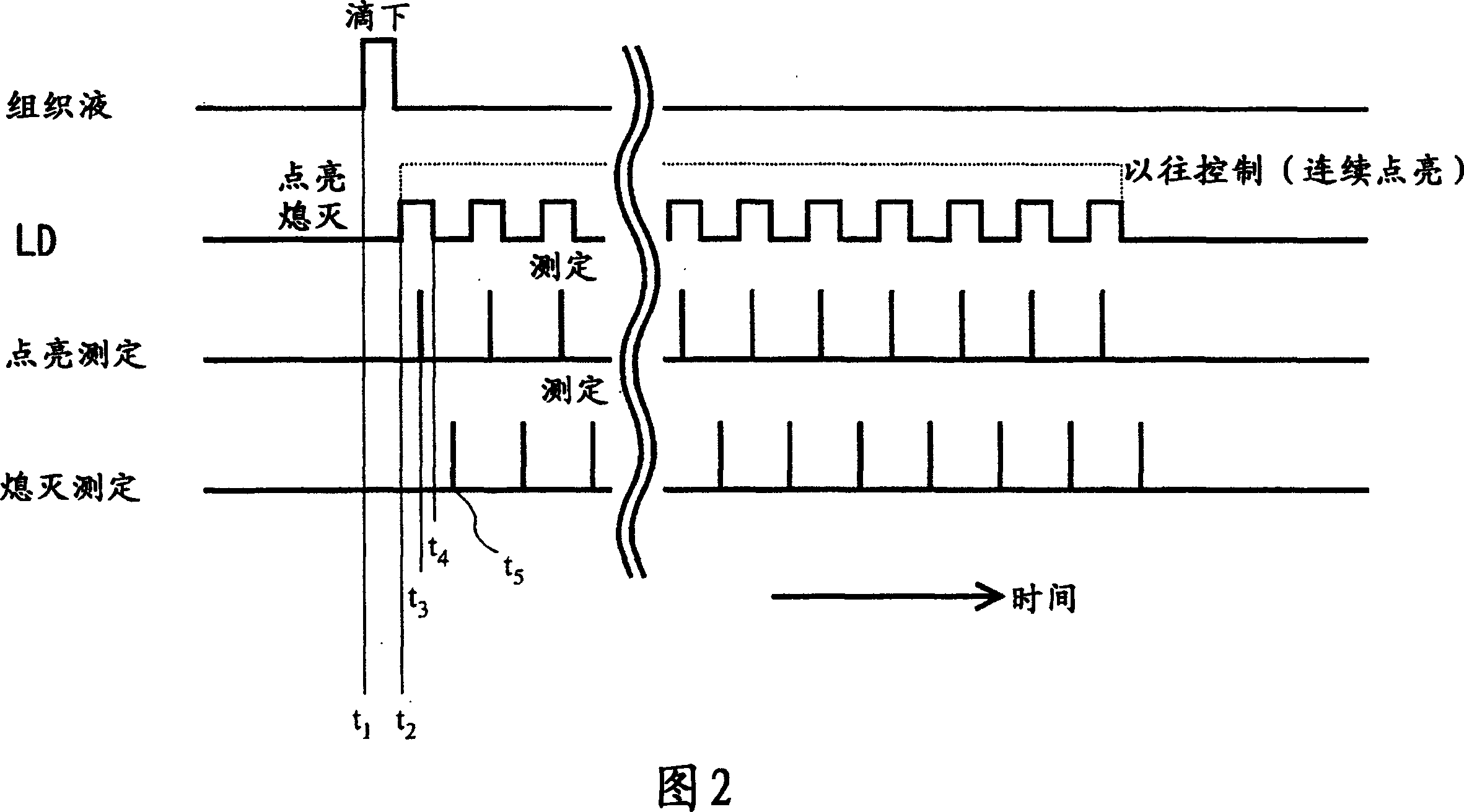
[0031] Light from a laser diode or the like used in this embodiment has extremely high coherence, and such highly coherent light tends to change in wavelength shift and spectral distribution due to temperature changes. If such light sensitive to temperature changes is used, the reliability of the measurement results will decrease if there is a temperature change during the measurement. In the present embodiment, in the optical inspection device, by suppressing the temperature rise of the light source serving as the heat source for the sensor chip, the decrease in the accuracy of the inspection result due to the temperature rise is avoided.
[0032] (check device)
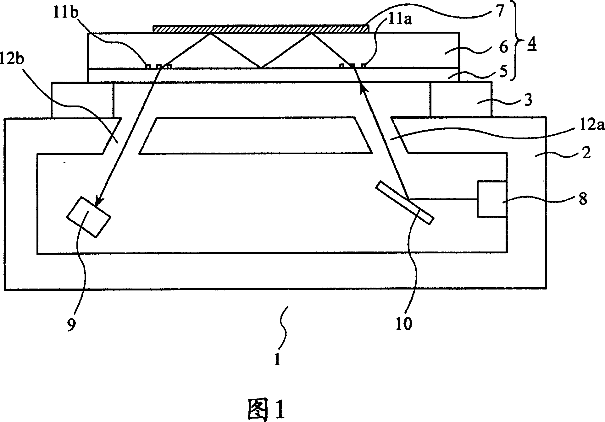
[0033] Hereinafter, the inspection apparatus of this embodiment is demonstrated using FIG. 1 which is a schematic diagram of the optical inspection apparatus of this embodiment.
[0034] In FIG. 1, 1 is an optical inspection device. This optical inspection device mainly includes a frame body 2 formed of a material ...
no. 2 Embodiment approach
[0055] The inspection device of this embodiment functions in such a manner that, in the inspection device of the first embodiment, before the inspection light irradiated from the light source is irradiated onto the sensor chip, it passes through the diffuser plate, so that the inspection light Even if the characteristics of the light change, even if the coherence is lowered, the ease with which the inspection light is affected by heat is eased, and even if the quality of the light beam output from the light source is changed, the change is moderated before it enters the chip.
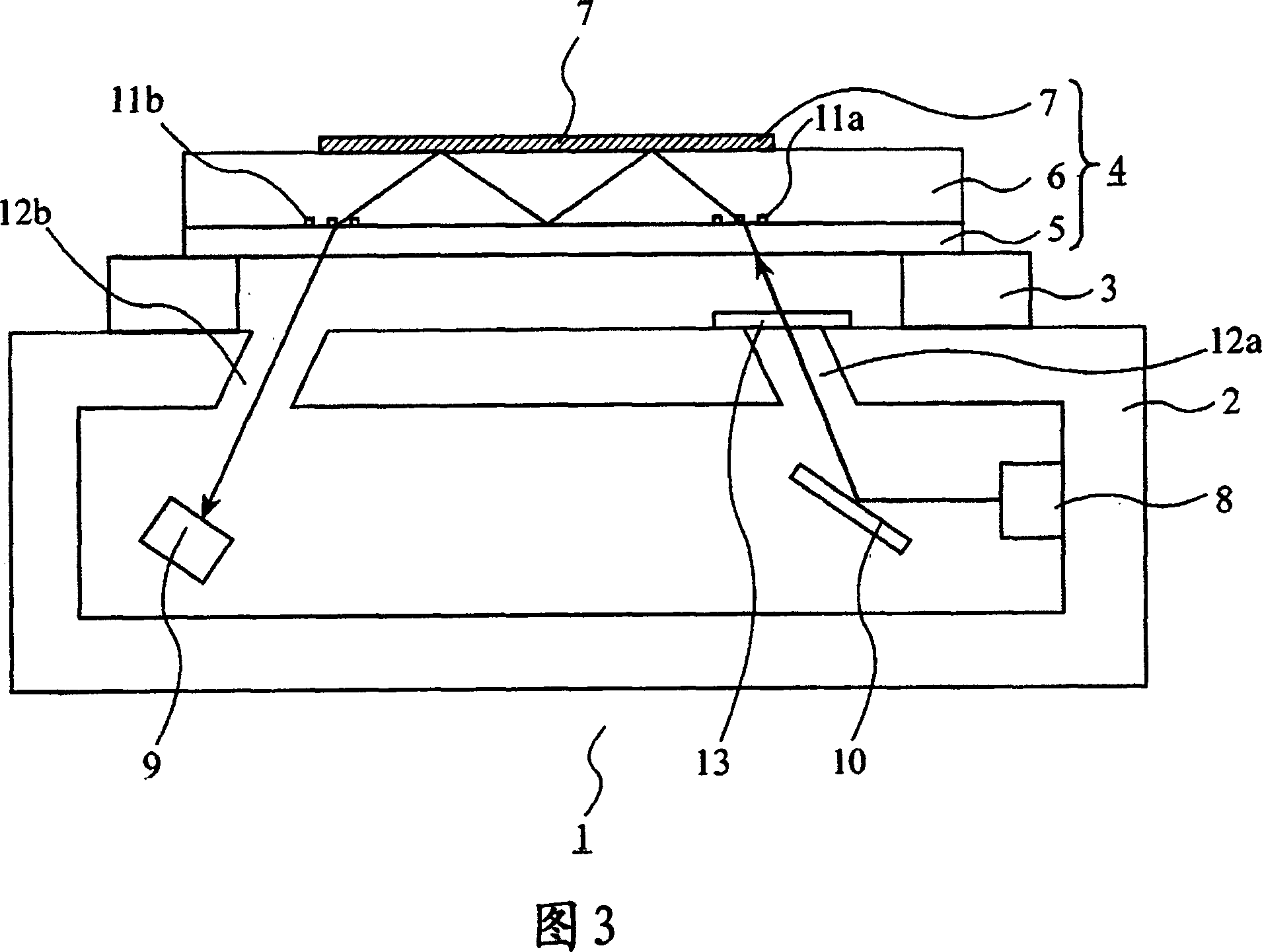
[0056] Hereinafter, the inspection device of this embodiment is shown in FIG. 3 which is a schematic cross-sectional view thereof. In FIG. 3 , the same components as those of the inspection device in FIG. 1 are assigned the same reference numerals, and detailed description thereof will be omitted.
[0057] As shown in FIG. 3, in this inspection device, the inspection light radiated from the light source...
no. 3 Embodiment approach
[0063] This embodiment is an embodiment for preventing the heat generated by turning on the light source from reaching the sensor chip, and is characterized in that the light source is fixed via a mechanism part that uses a material (thermal insulating material) with a thermal conductivity of 1.0 W / m·K or less. on the frame.
[0064] FIG. 4 shows a schematic diagram of the inspection device of this embodiment. In FIG. 4, components having the same functions as those in FIG. 1 are given the same reference numerals, and detailed descriptions thereof are omitted.
[0065] In the inspection device of the present embodiment, as shown in FIG. 4 , the light source 8 is fixed to the housing 2 by a fixing member 14 formed of a heat insulating material. Therefore, even if the external temperature of the optical inspection device changes, the heat is blocked by the thermally insulating fixing member 14 without affecting the temperature of the light source 8, and the change in the beam q...
PUM
| Property | Measurement | Unit |
|---|---|---|
| thermal conductivity | aaaaa | aaaaa |
Abstract
Description
Claims
Application Information
 - R&D
- Intellectual Property
- Life Sciences
- Materials
- Tech Scout
- Unparalleled Data Quality
- Higher Quality Content
- 60% Fewer Hallucinations
Browse by: Latest US Patents, China's latest patents, Technical Efficacy Thesaurus, Application Domain, Technology Topic, Popular Technical Reports.
© 2025 PatSnap. All rights reserved.Legal|Privacy policy|Modern Slavery Act Transparency Statement|Sitemap|About US| Contact US: help@patsnap.com