Method for preparing in-situ growing carbon nano tube chemical decoration electrode

A technology of in-situ growth of carbon nanotubes, applied in the direction of material electrochemical variables, etc., can solve the problems of adverse effects on the electrochemical performance of carbon nanotube chemically modified electrodes, insufficient bonding of the contact interface, and large contact resistance, etc., to achieve electron transfer Fast speed, small contact resistance and large response current

Inactive Publication Date: 2011-03-30
SOUTHWEST JIAOTONG UNIV
View PDF0 Cites 0 Cited by
  • Summary
  • Abstract
  • Description
  • Claims
  • Application Information

AI Technical Summary

Problems solved by technology

The contact resistance between the external substances such as the binder used and the carbon nanotubes and the solid electrode substrate is large, and the combination between the contact interface is not strong enough, which will affect the electrochemical performance of the generated carbon nanotube chemically modified electrode. performance has an adverse effect, causing it to degrade

Method used


Image

  • Method for preparing in-situ growing carbon nano tube chemical decoration electrode
  • Method for preparing in-situ growing carbon nano tube chemical decoration electrode
  • Method for preparing in-situ growing carbon nano tube chemical decoration electrode

Examples


Embodiment 1

[0023] a) Prepare and attach catalyst particles on solid electrode graphite by impregnation method: first, citric acid (C 6 h 8 o 7 ·H 2 O) was added to 20% Ni(NO 3 ) 2 solution, C 6 h 8 o 7 ·H 2 O (analytically pure) and Ni (NO 3 ) 2 ·6H 2 The molar ratio of O (analytically pure) is 2: 1 to make impregnating liquid; Then the graphite sheet (1cm * 8cm) as solid electrode is put into above-mentioned impregnating liquid and dipped for 20 minutes, then kept at 150 ℃ for 5 minutes; impregnated Repeat the heat preservation operation 5 times, after the last heat preservation, perform ultrasonic cleaning, and then heat preservation at 200°C for 1 hour. That is, a graphite electrode with a particle diameter of 1-100 nm particle metal nickel catalyst adhered on the surface is obtained.

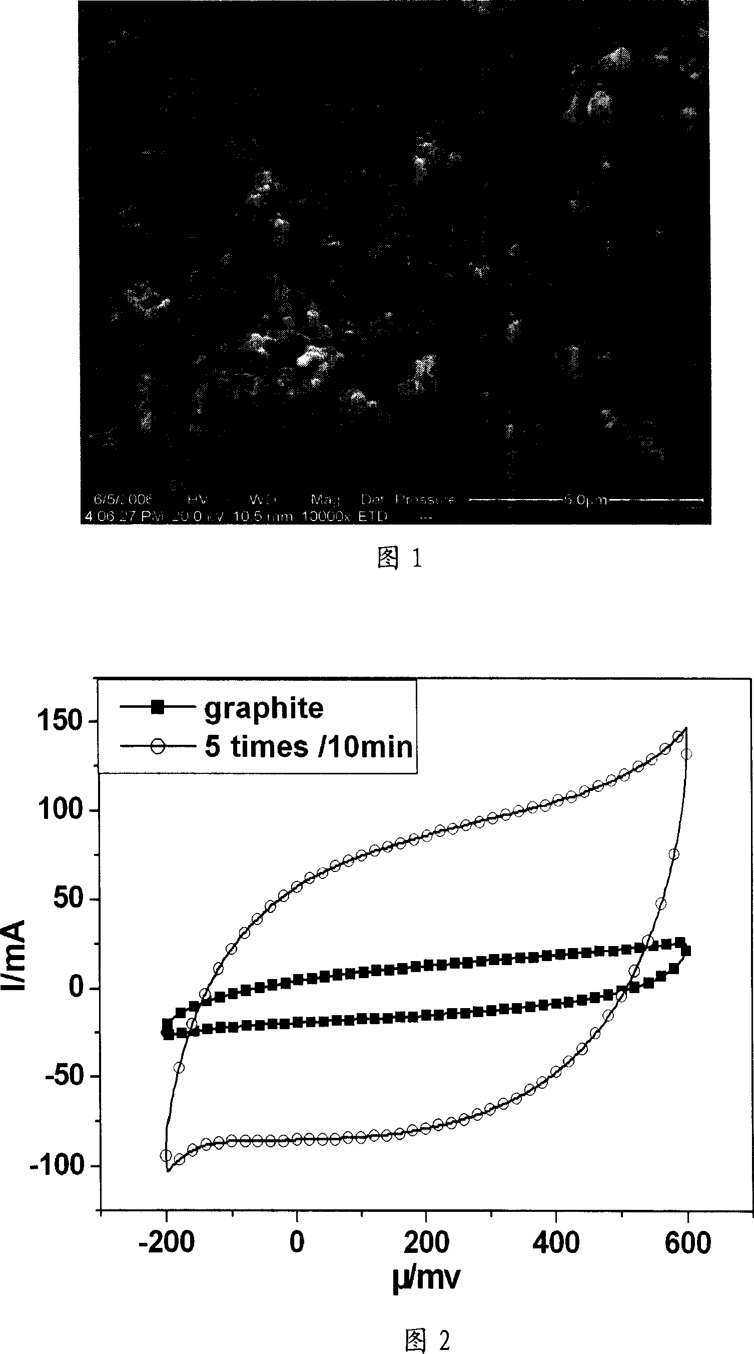
[0024] b) In-situ growth of carbon nanotubes on solid electrodes by chemical vapor catalytic cracking: put the above graphite electrodes attached with nickel catalysts into a horizontal tub...

Embodiment 2

[0027] The method of this example is basically the same as the preparation method of Example 1, the difference is only: do not add citric acid, but adopt Co(NO 3 ) 2 and Ni(NO 3 ) 2 The mixed solution of Co(NO 3 ) 2 and Ni(NO 3 ) 2 The molar ratio is 1:1. The graphite electrode is impregnated to obtain the graphite electrode with particle diameters of 1-100nm particle metal nickel and cobalt catalyst attached to the surface. The carbon source for growing carbon nanotubes is CH 4 . The shielding gas is argon.

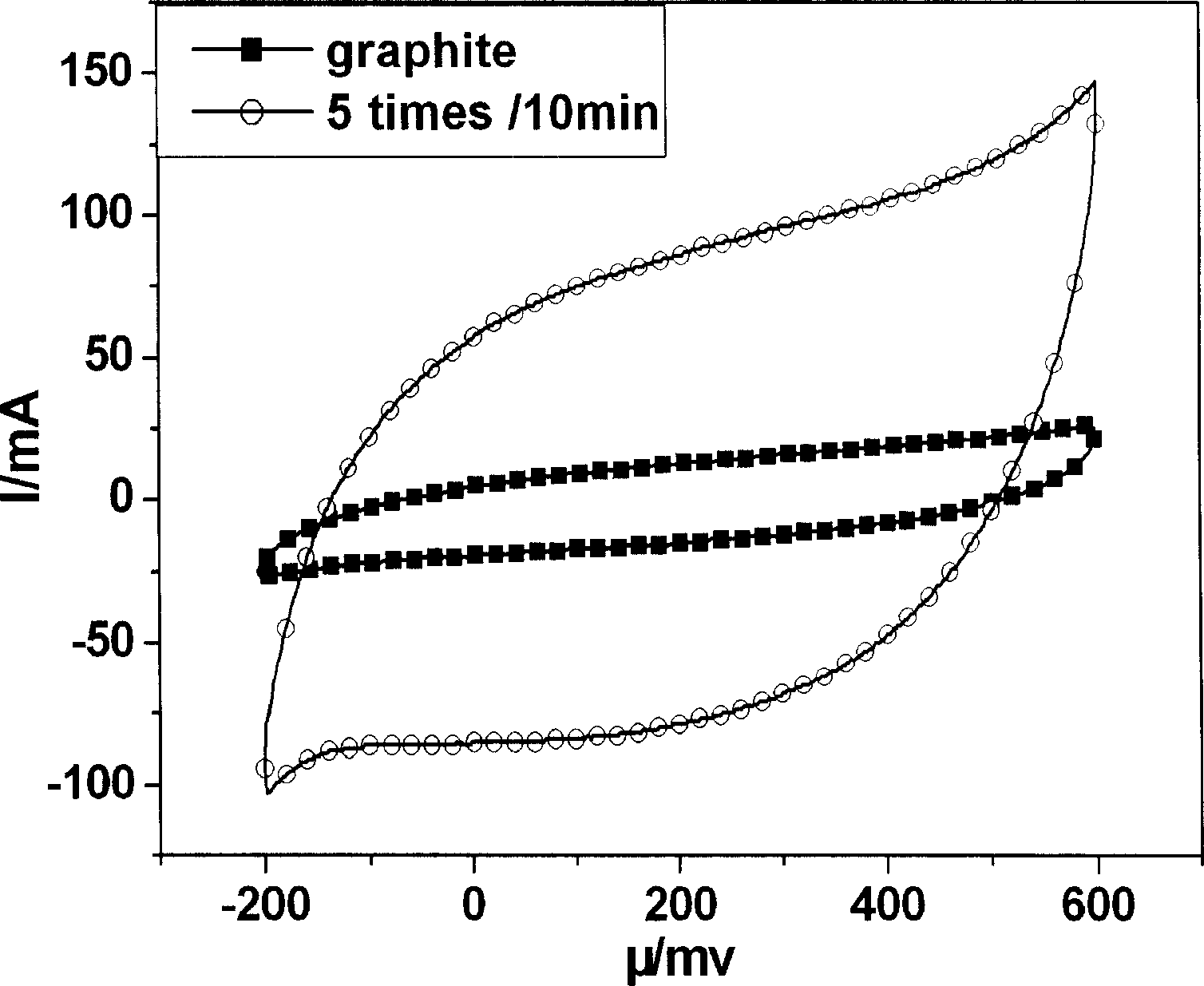
[0028] Fig. 3 is the in situ growth carbon nanotube chemically modified graphite electrode prepared by the method of this example at 0.01M[Fe(CN)] 4- +0.01M[Fe(CN)] 3- Cyclic voltammetry curves at different voltage scanning speeds (in mv / s) in the mixed solution of +0.5M KCl. Figure 4 is at 0.01M[Fe(CN)] 4- +0.01M[Fe(CN) 3- The relationship between the oxidation current and the square root of the voltage scanning speed in the mixed solution of +0.5M KCl. ...

Embodiment 3

[0030] The method of this example is basically the same as the production method of Example 1, the difference is only: do not add citric acid, but use Co(NO 3 ) 2 , Fe(NO 3 ) 3 and Ni(NO 3 ) 2The mixed solution of Co(NO 3 ) 2 , Fe(NO 3 ) 3 and Ni(NO 3 ) 2 The molar ratio is equal to 1:1:1. The graphite electrode is impregnated to obtain the graphite electrode with particle diameters of 1-100nm particle metal nickel, cobalt and iron catalyst attached to the surface. The carbon source for growing carbon nanotubes was n-hexane (C 6 h 14 ).


PUM

PropertyMeasurementUnit
particle diameteraaaaaaaaaa

Abstract

Using immersion method, magnetron sputtering method or electroplating method prepares catalyst in use for Nano carbon tubes to be developed attached to surface or shallow layer on surface of solid electrode. Then, carbon source are developed to Nano carbon tubes in situ of electrode catalyst attached to. Advantages are: good electrochemistry performance and detection performance of electrode chemical modified by Nano carbon tubes.

Description

Technical field [0001] The invention relates to a preparation method of a chemically modified electrode, in particular to a preparation method of an in-situ grown carbon nanotube chemically modified electrode. Background technique [0002] Carbon Nanotubes (CNT) are hollow thin tubes composed of coaxial cylindrical tubes composed of carbon atoms. The distance between adjacent coaxial cylindrical tubes is about 0.34nm, and the tube wall is composed of hexagonal carbon atoms. Each carbon atom is adjacent to three surrounding carbon atoms. The diameter of the tube is a few tenths of nanometers to tens of nanometers. The diameter, length and crimping angle of the tube vary with the preparation method and conditions. Due to the different angles and diameters of the crimp, its structure is different, resulting in its different performance. Because of these unique structures, carbon nanotubes have very peculiar chemical, physical, electronic and mechanical properties, which make...

Claims


Application Information

Patent Timeline
Patent Type & Authority Patents(China)
IPC IPC(8): G01N27/30
Inventor 江奇宋利君赵勇
Owner SOUTHWEST JIAOTONG UNIV
Why Eureka
Try Eureka