Device for realizing light beam automatic shaping using shape changing lens

A deformable mirror, beam technology, applied in optics, optical components, instruments, etc., to achieve the effect of large dynamic travel range, small nonlinear lag, and correction of high-order aberrations

Inactive Publication Date: 2007-06-27
INST OF OPTICS & ELECTRONICS - CHINESE ACAD OF SCI
View PDF0 Cites 25 Cited by
  • Summary
  • Abstract
  • Description
  • Claims
  • Application Information

AI Technical Summary

Problems solved by technology

[0004] The technical problem of the present invention is to overcome the deficiencies of various existing laser beam shaping methods, and provide a device that uses a deformable mirror to rea

Method used


Image

  • Device for realizing light beam automatic shaping using shape changing lens
  • Device for realizing light beam automatic shaping using shape changing lens

Examples


Embodiment Construction

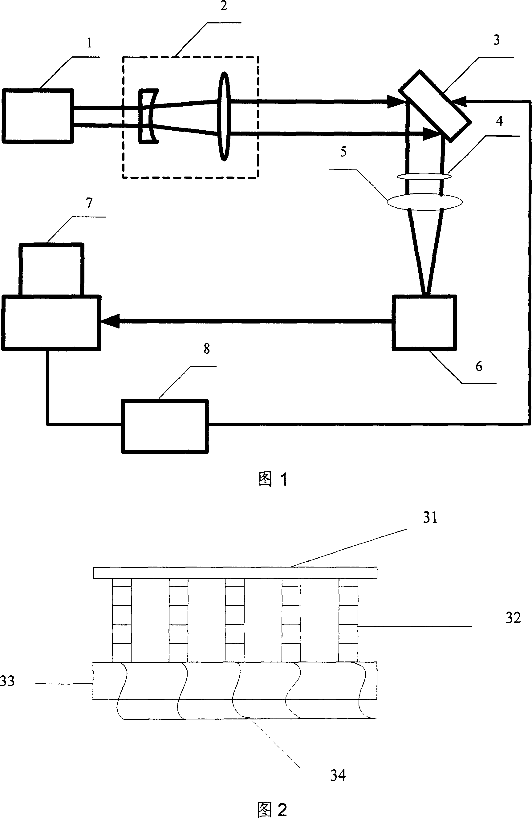
[0025] As shown in Figure 1, the device of the present invention that utilizes a deformable mirror to realize automatic beam shaping mainly includes a laser 1, a telescope 2, a deformable mirror 3, a variable density attenuation disk 4, a focusing lens 5, a CCD camera 6, a main control computer 7 and built-in other The internal image acquisition card, the control software based on genetic algorithm, the high-voltage amplifier 8 and the built-in D / A conversion card are composed. The output beam of the laser 1 is enlarged by the telescope 2 to match the aperture of the deformable mirror 3, and the beam is deformed. The mirror 3 is attenuated by the variable density attenuation disk 4 after reflection, then is incident on the focusing lens 5, and is converged on the target surface of the CCD camera 6 on the focal plane. The light spot signal on the surface is collected, and the absolute difference operation is performed on the corresponding pixel by using this signal and the targe...


PUM


Abstract

The device is composed of laser, telescope, deformation lens, CCD camera, D/A conversion card, high voltage amplifier, variable density attenuation disc, main control computer, image collection card, focusing lens, and genetic control algorithm. Using genetic algorithm to control the deformation lens, changing phase distribution of near field wave surface of laser beam, the invention reaches the purpose of changing light spot form in far field. The invention can realizes shaping laser beam without need of calculating relational expression between shape of light spot in far field and phase in near field. Gauss laser beam can be shaped to super Gauss beam, quadrate beam etc needed in practical application. The invention also can implement correcting static and quasi-static aberration included in laser beam effectively. Features are: simple structure, good generality, and easy of implementation. The invention is applicable to situation requiring specific shape of laser beam.

Description

technical field [0001] The invention relates to an adaptive optics device, which is an adaptive optics device which uses a piezoelectric ceramic deformation mirror to automatically shape the beam of a continuous laser. Background technique [0002] Since the advent of lasers, they have been widely used in many fields. In most fields, lasers are only required to output good-quality laser beams; however, in some specific fields, there are special requirements for the shape of laser output beams. Generally speaking, the energy of the far-field focal spot of an ideal Gaussian beam is only 84% of the total energy within one diffraction limit, and about 16% of the total energy is in its side lobes. In fact, the side lobes The existence of often affects the successful application of laser beams in certain fields. Compared with Gaussian beams, super-Gaussian beams, square beams and other shapes of beams have less sidelobe effects. The application of such beams in some industrial ap...

Claims


Application Information

Patent Timeline
IPC IPC(8): G02B26/06G02B27/00G06N3/12
Inventor 杨平许冰杨伟陈善球胡诗杰刘渊
Owner INST OF OPTICS & ELECTRONICS - CHINESE ACAD OF SCI
Why Eureka
Try Eureka