
Permanent magnet mechanism contactor with parallel magnetic path

A permanent magnet mechanism and contactor technology, applied in electromagnetic relays, electromagnetic relay details, circuits, etc., can solve the problems of reducing electromagnetic force, failure to achieve voltage-loss breaking, cost-consuming, etc., and achieve the effect of reducing power consumption

Inactive Publication Date: 2007-06-27
XI AN JIAOTONG UNIV
View PDF3 Cites 11 Cited by
  • Summary
  • Abstract
  • Description
  • Claims
  • Application Information

AI Technical Summary

Problems solved by technology

[0004] 1. For the energy-saving permanent magnet mechanism contactor studied by the predecessors, although the energy-saving effect is relatively obvious, due to the need for a special device to realize the voltage loss protection function, and even if it is equipped with a special voltage loss protection device, sometimes it cannot achieve complete protection. The loss of voltage breaking protection function, so the work reliability is not high
For example, the patent number is 97220287.0, and the patent name is "micro-consumption energy-saving absorption and release device", and the patent number is 200410017488.5, and the patent name is "permanent magnetic pulse contactor". Noise and other general characteristics, but a special voltage loss protection device is required to realize the voltage loss protection function, which not only costs a certain amount of cost, but also cannot achieve 100% voltage loss breaking
After a long-term power failure, when the contactor is accidentally closed and needs to be disconnected, the contactor cannot be disconnected because the control circuit has no energy storage
[0005] 2. For the permanent magnet mechanism contactor with series magnetic circuit and without voltage loss protection studied by predecessors [5] , because the permanent magnet attraction is smaller than the spring reaction force at the closing position, and the other part of the attraction is provided by the electromagnetic attraction generated by the energized coil, which reduces the electromagnetic force provided by the energized coil and has a certain energy-saving effect, but it is low in this structure. The permanent magnet with magnetic permeability is connected in series in the magnetic circuit, which increases the reluctance in the magnetic circuit, undoubtedly increases the number of ampere turns of the coil, increases the energy consumption of the excitation, and the energy saving effect is not ideal

Method used


Image

  • Permanent magnet mechanism contactor with parallel magnetic path
  • Permanent magnet mechanism contactor with parallel magnetic path
  • Permanent magnet mechanism contactor with parallel magnetic path

Examples


Embodiment Construction

[0037] 1. The overall idea of ​​the technical solution

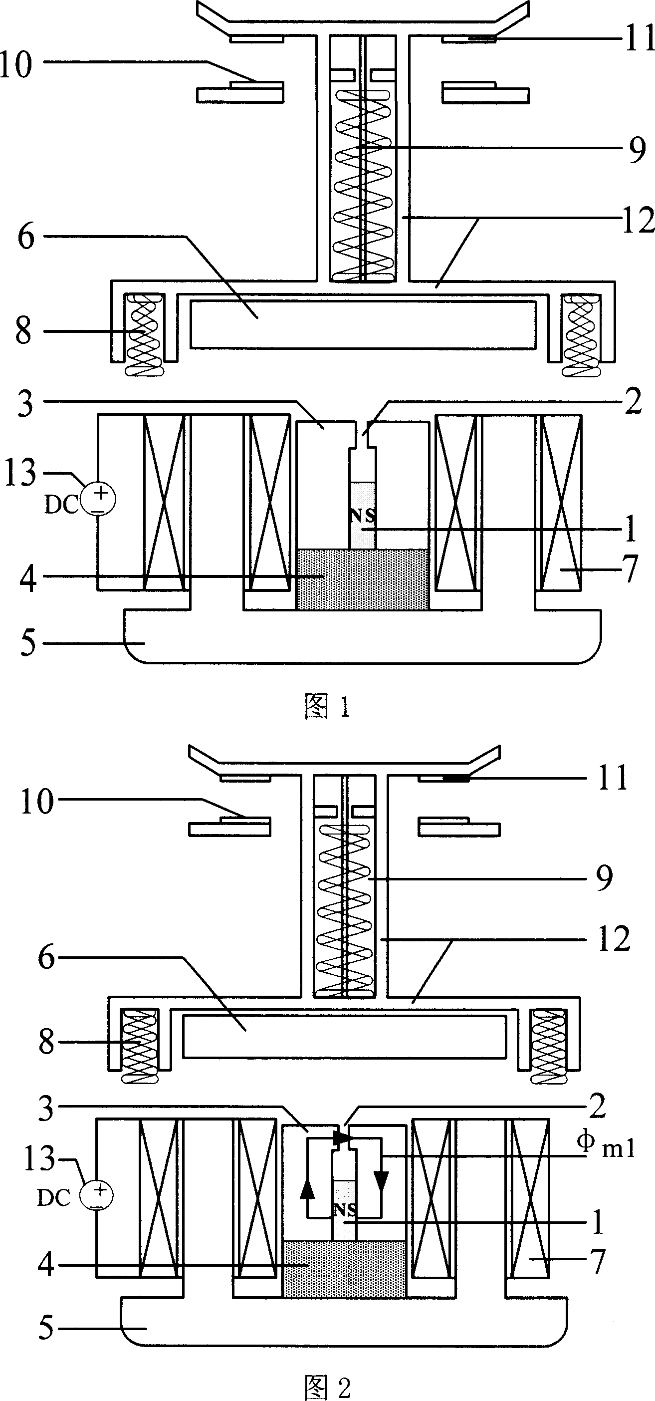
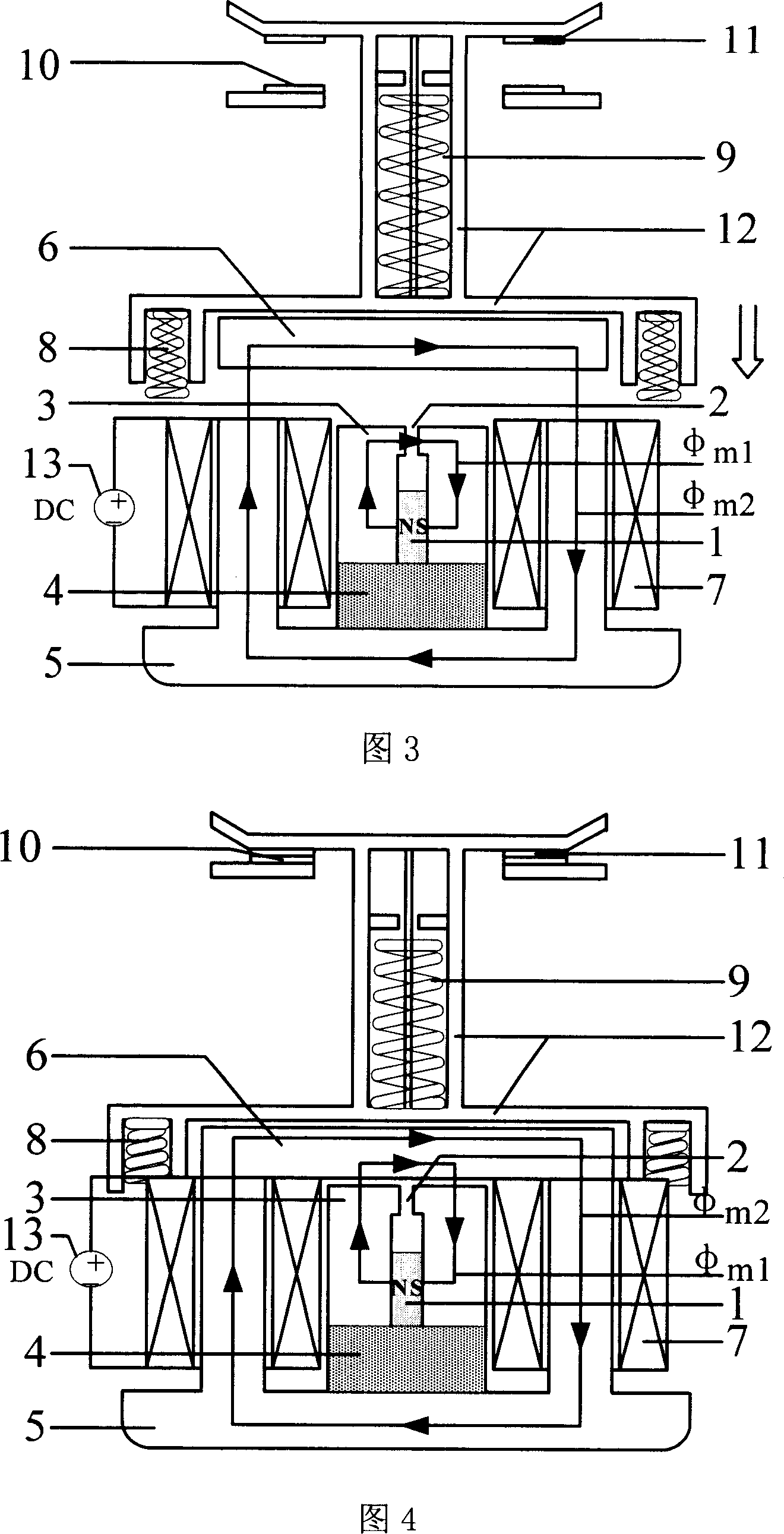
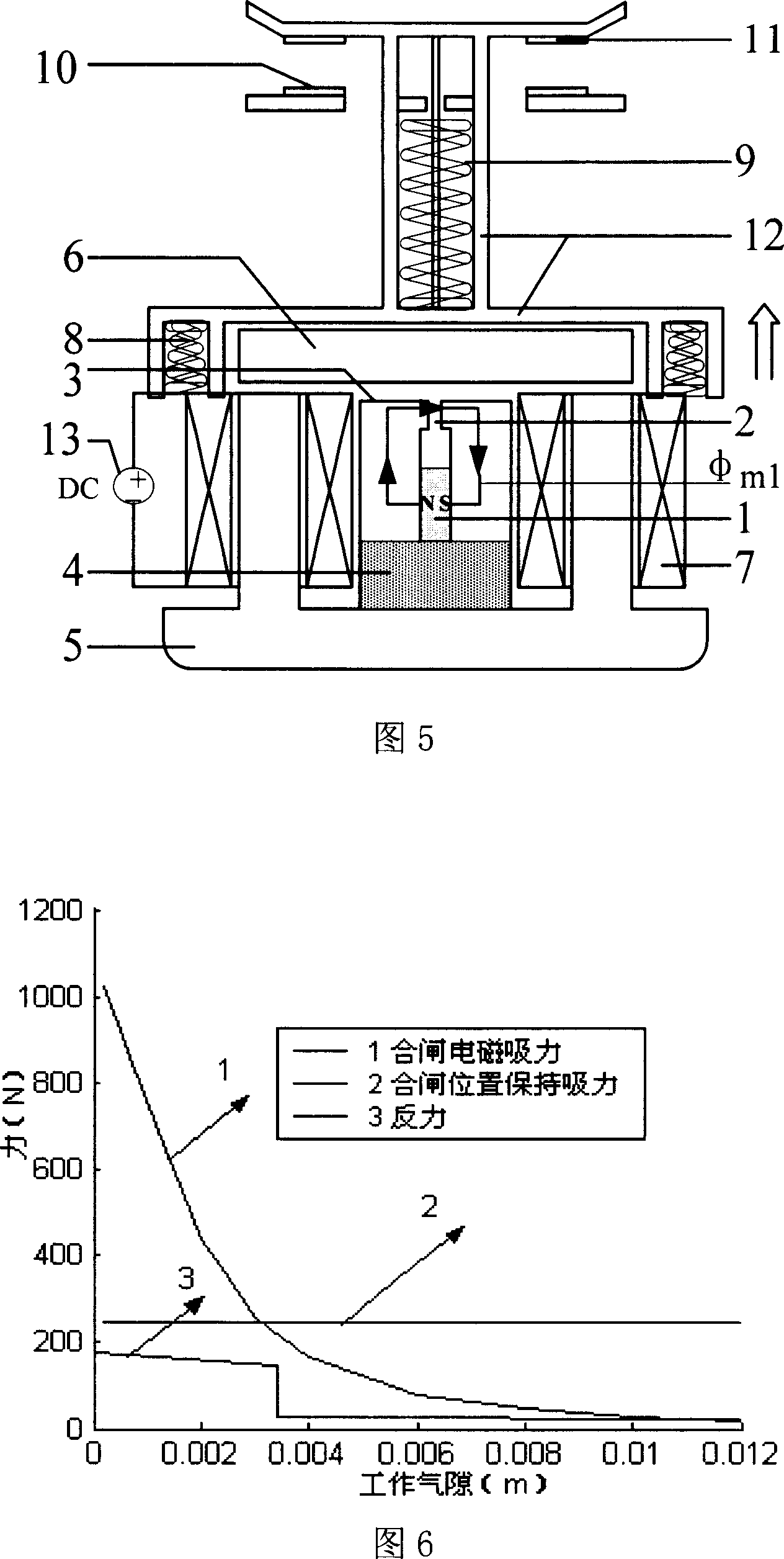
[0038] Reducing the working energy and power consumption of contactors and improving the working reliability of contactors have always been the important goals of contactor research. So far, neither the traditional electromagnetic contactor nor the existing permanent magnet contactor has satisfactorily solved this proposition. The design concept of the present invention is to propose a new permanent magnet mechanism contactor with a parallel magnetic circuit to realize the energy saving of the permanent magnet mechanism contactor and the function of voltage loss protection without the need for a voltage loss protection device.

[0039] 1) A new permanent magnet mechanism contactor with a parallel magnetic circuit:

[0040] At present, many types of permanent magnet mechanism contactors for energy saving have been developed, but because the previous energy-saving permanent magnet mechanism contactors have no pull-in and ...


PUM


Abstract

This invention discloses a magnet unit contactor with parallel magnetic circuit, which replaces the magnetic operation unit of an original contactor to a magnet operation unit, in which, the static core of the unit includes a U-static core, a magnet and a magnetic circuit static core, both ends of the static core are fixed with serial excitation coil, the magnet is inserted in the static core, when the structure is at the kept position, it overcomes the absorption force of the counter spring force, which is borne by the electromagnetic absorption and magnet absorption and the contactor is at the closed position, since parallel circuit is applied, flux generated by the serial excitation coil and that generated by the magnet flow through different paths separately, and the serial excitation coil flux passes through the minimum magnetic resistance to save energy of the magnet contactor.

Description

technical field [0001] The invention belongs to the field of low-voltage electrical appliances for power transmission and distribution equipment, and relates to a contactor, in particular to a new low-power consumption permanent magnet mechanism contactor with a parallel magnetic circuit. Pressure protection function. Background technique [0002] At present, the contactors widely used in the field of low-voltage electrical appliances are generally electromagnetic contactors. When the electromagnetic contactor is working, there are disadvantages such as large noise and frequent contact bounce, especially when the electromagnetic operating mechanism is in the closing state, the excitation coil needs to be connected to the alternating current for a long time, which not only causes a large iron loss and magnetic ring loss , so that the temperature of the coil core rises, causing the coil to burn easily and wasting a lot of electric energy. For a long time, around reducing the...

Claims


Application Information

Patent Timeline
IPC IPC(8): H01H51/00H01H51/01H01H50/36H01H50/42H01H47/02
Inventor 荣命哲刘懿莹娄建勇王小华吴翊
Owner XI AN JIAOTONG UNIV
Learn More