
Lens cleaning equipment

A technology for cleaning jigs and lenses, which is applied to cleaning methods and tools, manufacturing tools, cleaning flexible objects, etc., can solve the problems of low cleaning efficiency, unclean lens cleaning, lens damage, etc., and achieve the effect of improving the efficiency of glue removal

Inactive Publication Date: 2007-07-04
HONG FU JIN PRECISION IND (SHENZHEN) CO LTD +1
View PDF1 Cites 1 Cited by
  • Summary
  • Abstract
  • Description
  • Claims
  • Application Information

AI Technical Summary

Problems solved by technology

[0004] However, when using the cleaning box 31 to clean multiple lenses at the same time, the lenses will not be cleaned cleanly due to mutual adhesion, and may cause multiple lenses to collide with each other and be damaged, so the cleaning efficiency is low

Method used


Image

  • Lens cleaning equipment
  • Lens cleaning equipment
  • Lens cleaning equipment

Examples


Embodiment Construction

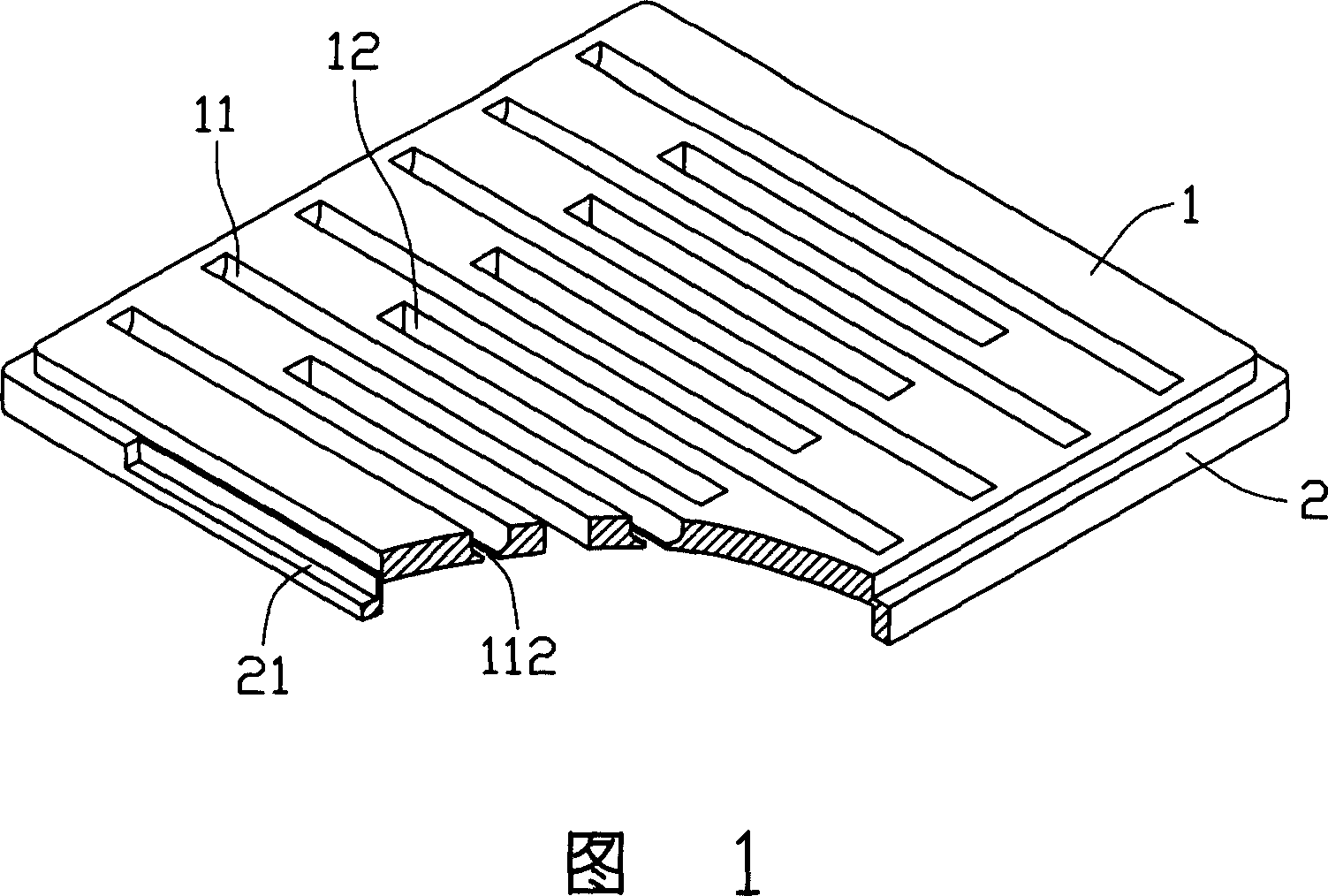
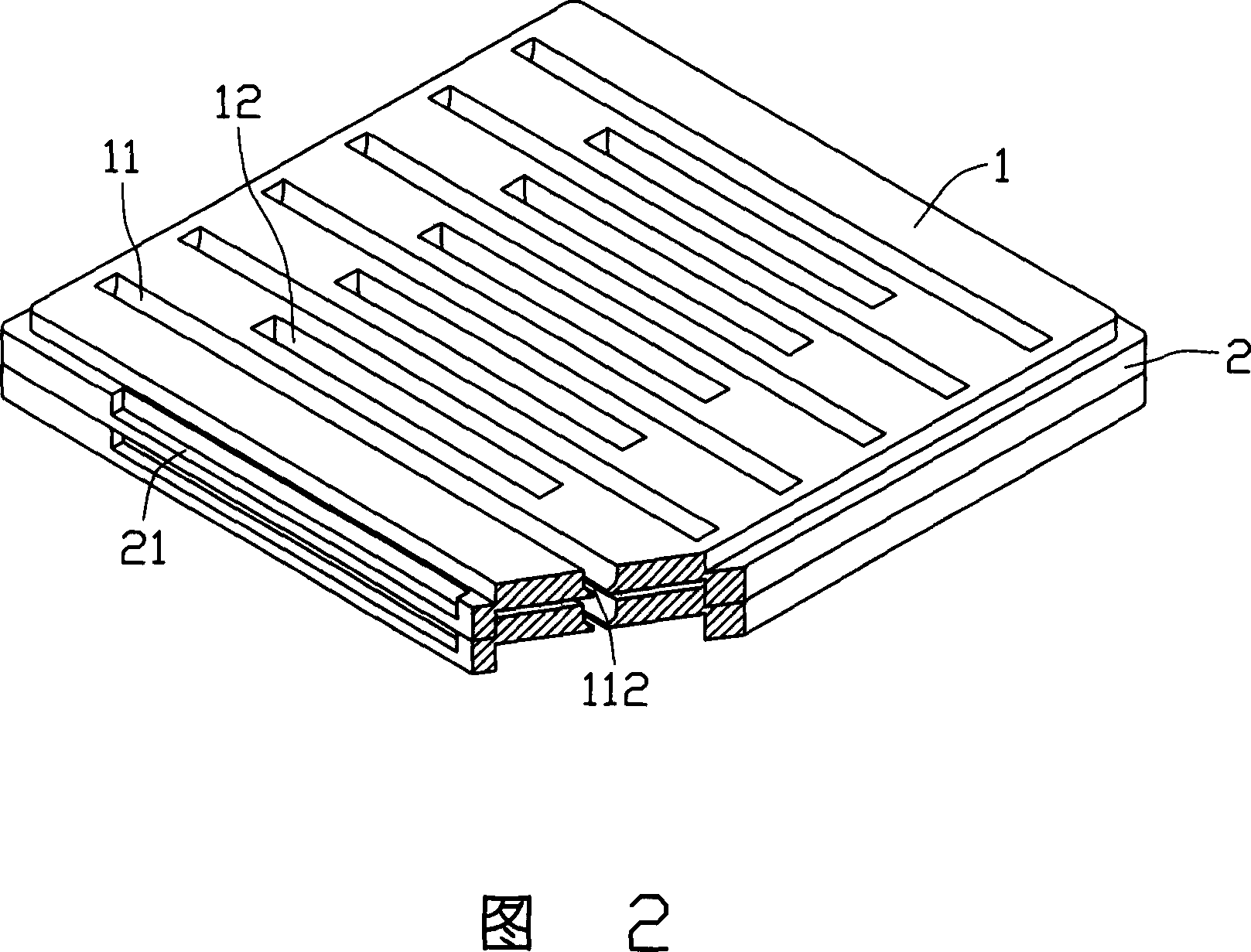
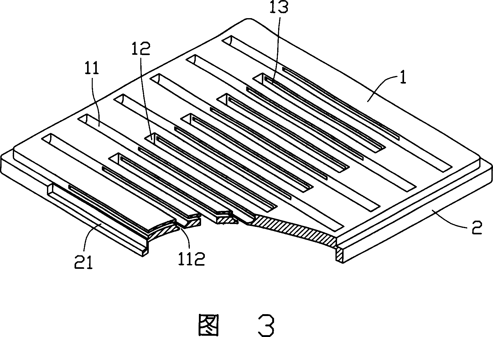
[0012] Please refer to FIG. 1 , the lens cleaning jig according to the preferred embodiment of the present invention is square, and includes a main body 1 and a frame 2 .

[0013] The main body 1 is a square plate body, on which a plurality of accommodating grooves 11 and a plurality of adhesive removing solvent channels 12 are separated. The accommodating grooves 11 are used for accommodating the cylindrical glued body of the lens to be cleaned, and its width is consistent with the diameter of the lens to be cleaned. The groove bottom of each accommodation groove 11 is opened with an opening 112 along its extending direction, and the width of the opening 112 is smaller than the diameter of the lens to be cleaned. The glue-removing agent flow channel 12 opens two opposite surfaces of the main body 1 , and the accommodating grooves 11 and the glue-removing agent flow channels 12 are arranged on the main body 1 at a distance from each other.

[0014] The frame 2 is a frame, whi...


PUM


Abstract

A device of cleaning lenses which is used for cleaning lens, it has one main body, and the main body is equipped with several containing channel, the containing channel is used for contains cleaning lenses, the bottom of the containing channel has an opening. The lens clean device can wash many lenses at one time, improves the lens efficiency of removing gel.

Description

【Technical field】 [0001] The invention relates to a lens cleaning jig. 【Background technique】 [0002] Optical elements such as optical filters and optical lenses are widely used in digital camera systems. Since the lens barrels of the above-mentioned digital camera systems are mostly circular, the optical lenses used often need to be processed into circular shapes. In the current optical lens manufacturing process, usually the coated mother sheet is first cut into small squares, and then the lens is rounded by a rounding machine, and then cleaned. [0003] Ordinary optical lens cleaning usually only needs to put the lens into clean water, clean it with ultrasonic vibration and then dry it. Please refer to FIG. 4 , Chinese Patent No. 99234336.4 discloses an ultrasonic cleaning machine, which is composed of a cleaning box 31 , a casing 32 and a movement 33 . The cleaning box 31 is a small sealed cylindrical container with a cover 34 , in which a deglue solvent 35 and a lens...

Claims


Application Information

Patent Timeline
IPC IPC(8): B08B11/00B08B13/00B25B11/00B08B3/04
Inventor 张耕铭
Owner HONG FU JIN PRECISION IND (SHENZHEN) CO LTD
Learn More