
ABS locking proof system controlling means

An anti-lock braking system and control device technology, applied in the direction of brakes, etc., can solve the problems of complex processing methods and long debugging period, and achieve the effect of simple method and short debugging period

Active Publication Date: 2007-07-04
BYD CO LTD
View PDF0 Cites 1 Cited by
  • Summary
  • Abstract
  • Description
  • Claims
  • Application Information

AI Technical Summary

Problems solved by technology

[0004] The purpose of the present invention is to solve the shortcomings of complex processing methods and long development and debugging cycles caused by using pulse width wheel speed as signal input in the prior art, and to provide an anti-lock braking system control system that utilizes input signals that vary linearly with wheel speed device

Method used


Image

  • ABS locking proof system controlling means
  • ABS locking proof system controlling means
  • ABS locking proof system controlling means

Examples


Embodiment Construction

[0015] Specific embodiments of the present invention will be described in detail below with reference to the accompanying drawings.

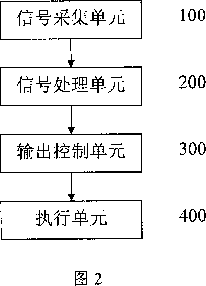
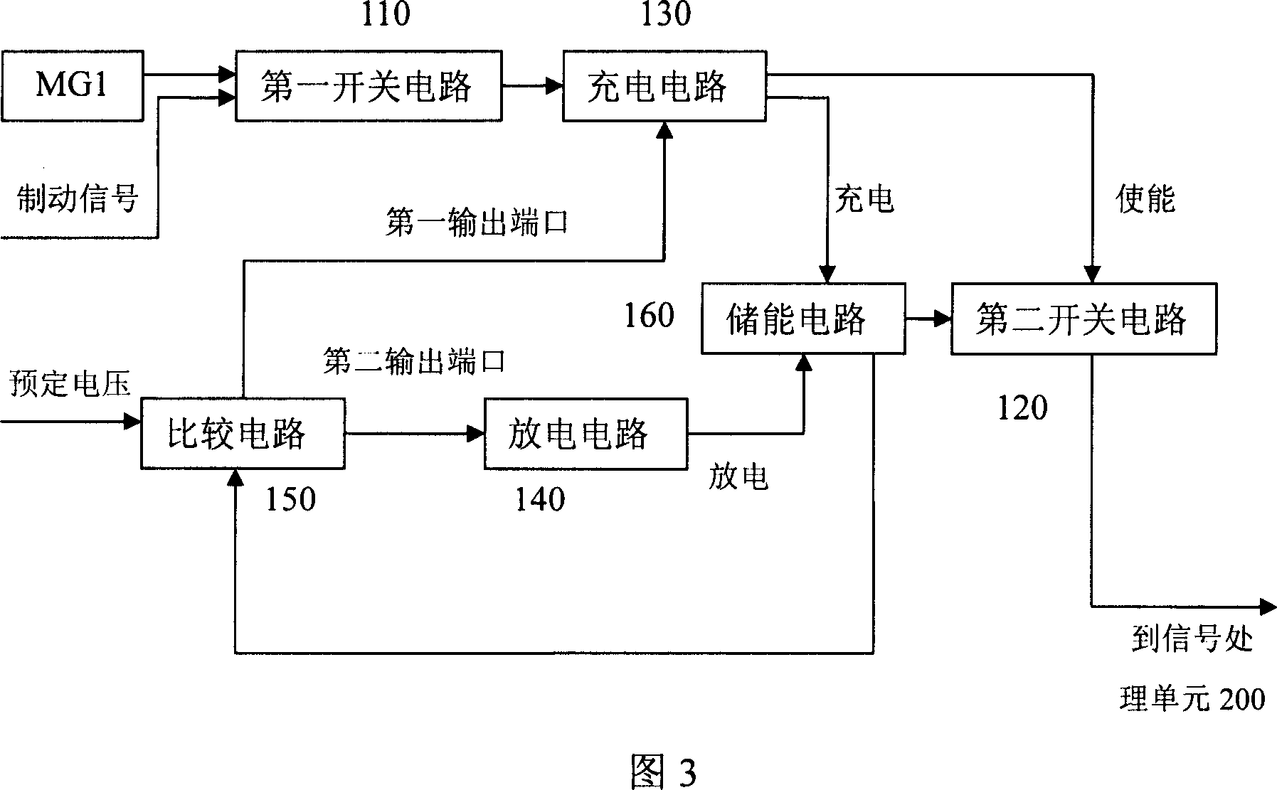
[0016] FIG. 2 is a block diagram of the anti-lock braking system control device according to the present invention. In the figure, the anti-lock braking system control device provided by the present invention includes: a signal acquisition unit 100 for collecting wheel speed signals, and generating signals linearly according to changes in wheel speed; a signal processing unit 200 for receiving the signal processing unit signal and convert the received signal into the acceleration signal of the wheel; the output control unit 300 is used to receive the acceleration signal and generate a decompression output and / or a pressure holding output; and an execution unit 400 is used to receive the The decompression output and / or the pressure maintenance output generated by the output control unit are used to adjust the braking force on the wheels.

[0017...


PUM


Abstract

The invention discloses a control device of ABS locking-proof system, which comprises the following parts: signal gathering unit (100), signal processing unit (200), output control unit (300) and executing unit (400), wherein the signal gathering unit (100) gathers wheel speed signal, which generates signal according to changing line of wheel speed; the signal processing unit (200) receives the signal of signal gathering unit (100), which switches the signal into acceleration signal of wheel; the output control unit (300) receives the acceleration signal, which generates decompressing output and / or pressurized output; the executing unit (400) receives decompressing output and / or pressurized output, which adjusts braking force of wheel.

Description

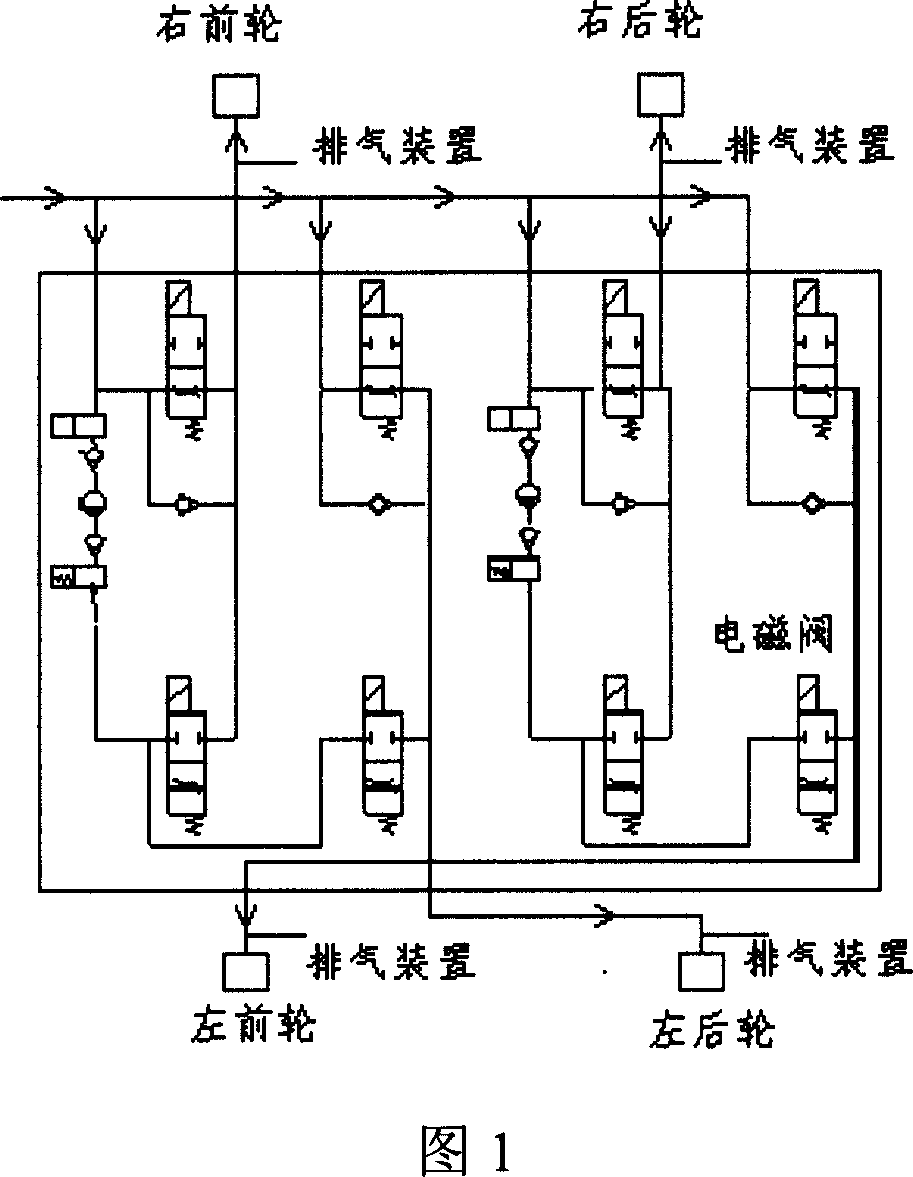
technical field [0001] The invention relates to a control device, in particular to a control device for an automobile anti-lock braking system. Background technique [0002] The ABS anti-lock braking system of automobiles has become an important technology to improve automobile safety. Figure 1 shows a schematic diagram of an ABS anti-lock braking valve body commonly used now. In the figure, the ABS valve body includes eight solenoid valves, and each solenoid valve has an electromagnetic coil. By energizing and disconnecting these electromagnetic coils, the Realize the opening and closing of the electromagnetic valve, so as to realize the control of the wheel braking force. Among them, every two electromagnetic coils cooperate to control a wheel, which can realize the pressure maintaining process, decompression process and increasing pressure during the braking process of the car. pressure process etc. Since these knowledge are well known to those skilled in the art, they ...

Claims


Application Information

Patent Timeline
Patent Type & Authority Applications(China)
IPC IPC(8): B60T8/17
Inventor 鲍海宝李维宏
Owner BYD CO LTD
Learn More