
Color filter array and organic light-emitting display device using the same

A color filter array and light-emitting display technology, which is applied in the fields of optical filters, instruments, optics, etc., can solve the problems of light reduction, complicated manufacturing process, poor color purity, etc., and achieve the effect of improving production efficiency

Active Publication Date: 2007-07-04
SAMSUNG DISPLAY CO LTD
View PDF0 Cites 15 Cited by
  • Summary
  • Abstract
  • Description
  • Claims
  • Application Information

AI Technical Summary

Problems solved by technology

[0005] The problem with the three-color luminescence method is that the lifetime of any one color determines the lifetime of the entire system, the problem with the filter method is that the amount of light is reduced because the color filter absorbs the white light, and the problem with the color conversion method is that the color conversion is excited by blue light material, thereby reducing the contrast
However, the problem with this color light-emitting device is that it uses three wavelengths with poor luminous efficiency and color purity of red light, the color coordinate value of the three-color light source is seriously deformed, and its manufacturing process is complicated.

Method used

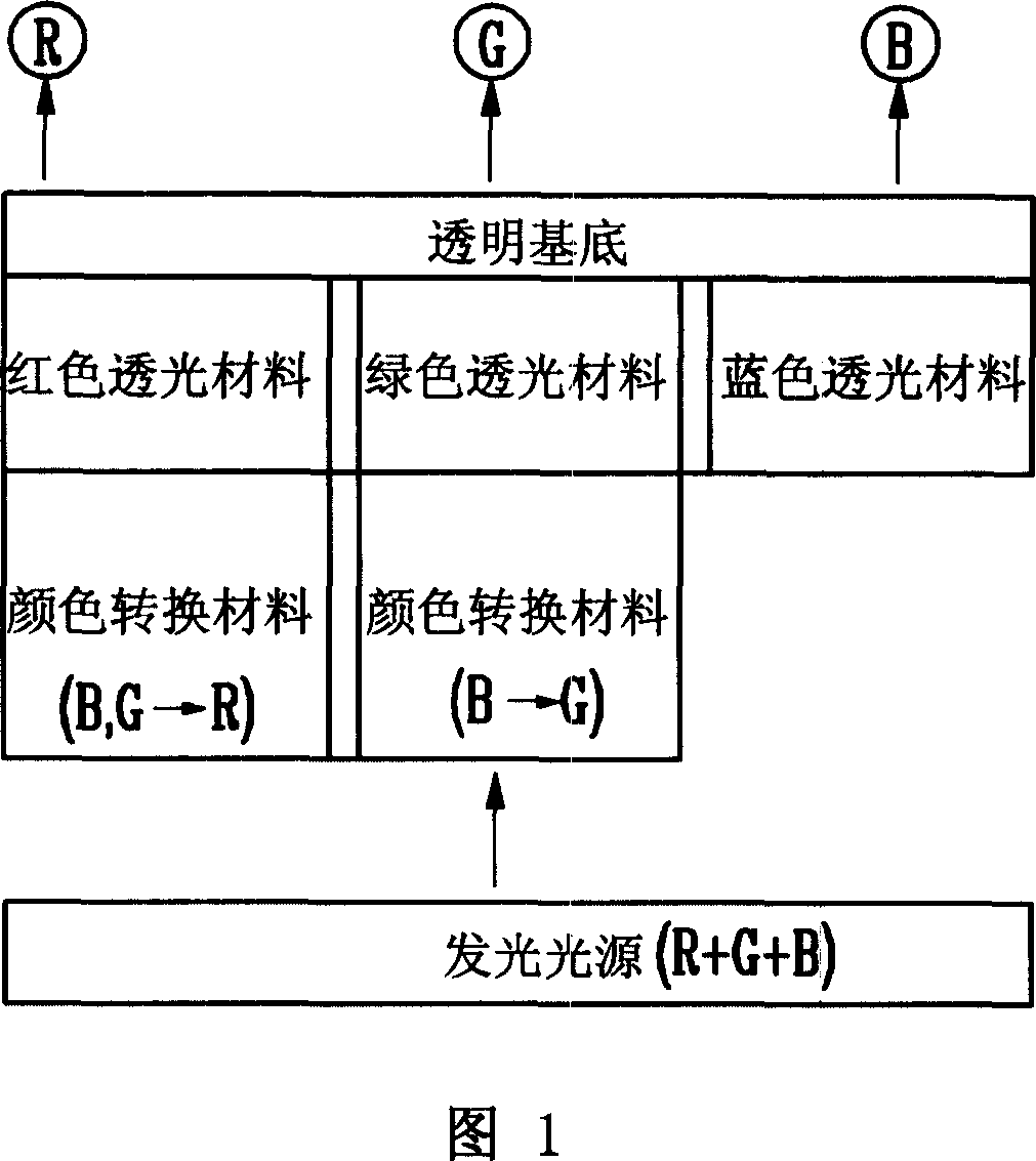

Image

  • Color filter array and organic light-emitting display device using the same
  • Color filter array and organic light-emitting display device using the same
  • Color filter array and organic light-emitting display device using the same

Examples


Embodiment Construction

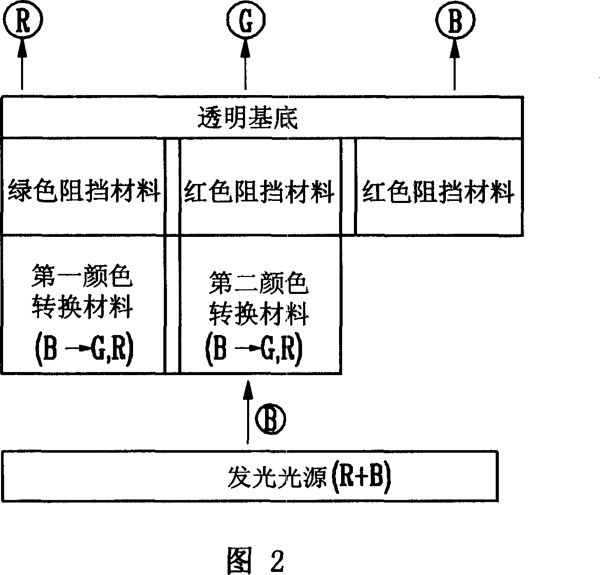
[0034] Hereinafter, an embodiment of a color filter array according to the present invention will be described in more detail with reference to FIG. 2 . FIG. 2 is a structural diagram of a color filter array according to an embodiment of the present invention. According to FIG. 2, the color filter array includes a transparent substrate, red color filters, green color filters and blue color filters. In one embodiment, the light emitting light source used in the color filter is a mixed blue and red light source. The luminescent light sources can be arranged in a single layer or in multiple layers. The X coordinate is in the range of 0.20 to 0.50 and the Y coordinate is in the range of 0.20 to 0.43.

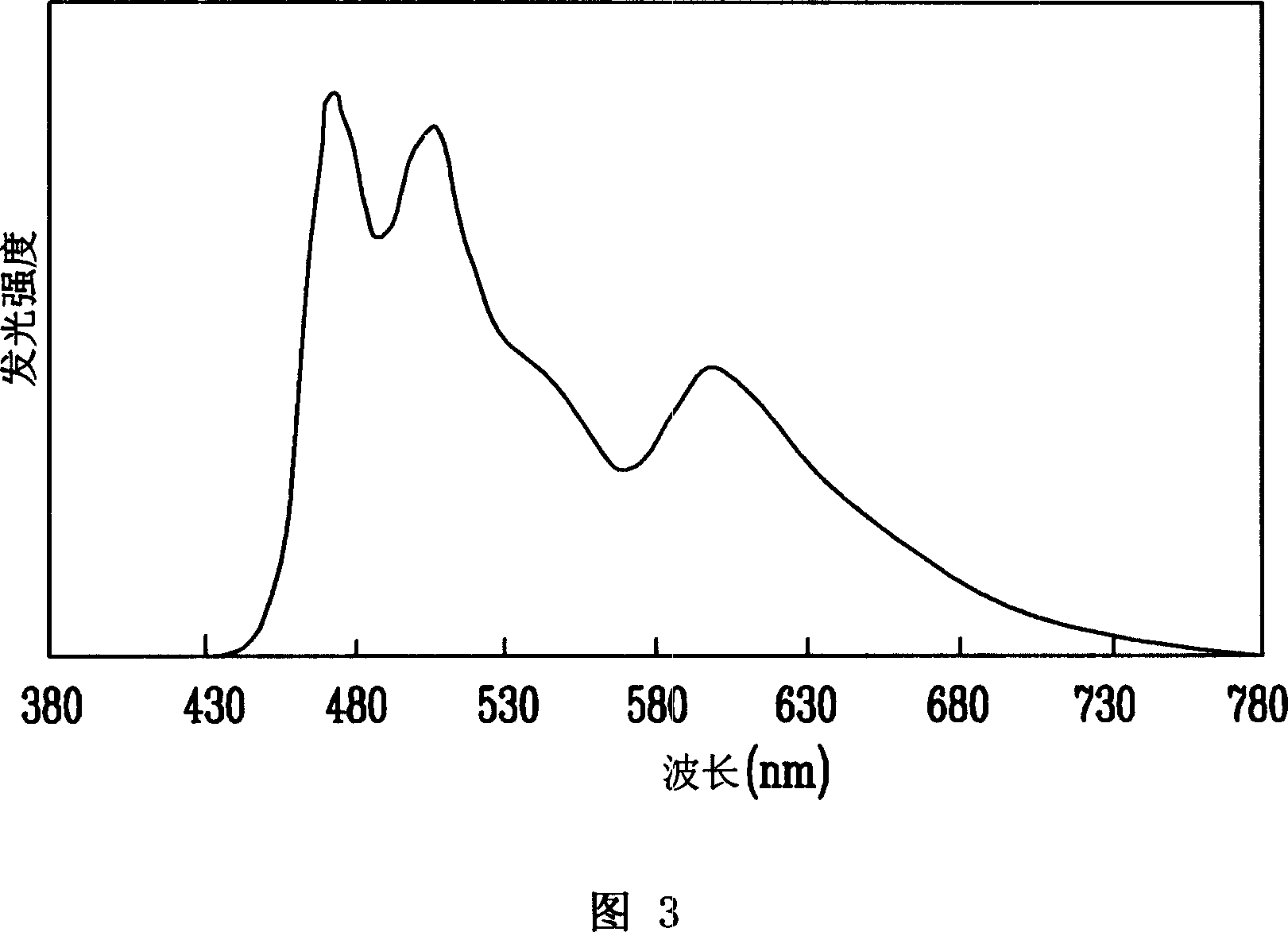
[0035] Fig. 3 has shown the emission spectrum of the light source adopted in the color filter of the embodiment that the light emitting source only emits blue light and red light. Little change, and easy to manufacture luminescent light source.

[0036] In one embodiment, the tr...


PUM

PropertyMeasurementUnit
Thicknessaaaaaaaaaa
Transmittanceaaaaaaaaaa

Abstract

A colour filter array is provided that is capable of implementing full colour with improved light-emitting efficiency and colour coordinate values from a mixed light of blue and red, and an organic light-emitting display device using the same. A colour filter array receiving a mixed light of blue wavelength light and red wavelength light to implement full colour according to an embodiment of the invention comprises a red filter, a green filter, and a blue filter. The red filter includes a first colour conversion material for converting the blue wavelength light into green light and red light and a green blocking material for blocking the green light. The green filter includes a second colour conversion material for converting the blue wavelength light into green light and red light and a red blocking material for blocking the red light. The blue filter includes a red blocking material for blocking the red wavelength light.

Description

[0001] This application claims the priority and benefit of Korean Patent Application No. 2005-131548, No. 2005-131549 and No. 2005-131550 filed in the Korean Intellectual Property Office on December 28, 2005, the entire disclosure of which is incorporated by reference here. technical field [0002] The present invention relates to a color filter array and a flat panel display device using the color filter array, more particularly, the present invention relates to a method capable of achieving improved luminous efficiency and color coordinates by mixed light of blue and red value of full-color color filter arrays and organic light-emitting display devices. Background technique [0003] In addition, the present invention relates to an organic light emitting display device in which a light emitting layer can be easily formed and a color coordinate value of the light emitting layer does not change greatly depending on driving vol...

Claims


Application Information

Patent Timeline
IPC IPC(8): G02B5/20G02B5/23H01L51/50H01L51/52H01L27/32
CPCH10K59/351H10K59/38H10K71/00
Inventor 梁承珏李昌浩金喜妍高熙周申定翰
Owner SAMSUNG DISPLAY CO LTD
Learn More