

Device and method for measuring quality factor of homology sampling
A quality factor, measuring device technology, applied in transmission monitoring/testing/fault measurement systems, electromagnetic wave transmission systems, electrical components, etc., can solve the problem of broadband optical frequency locking loops that are not easy to optical signal phase coherence, complexity and high equipment cost question
Inactive Publication Date: 2010-11-10
IND TECH RES INST
View PDF1 Cites 0 Cited by
- Summary
- Abstract
- Description
- Claims
- Application Information
AI Technical Summary
Problems solved by technology
The coherence detection module of the prior art, for example, US Patent No. US2005 / 0185255A1 published on August 25, 2005, its quality factor monitoring technology consists of a wavelength tunable optical pulse laser (wavelength tunable optical pulse laser) with the same wavelength as the measured optical signal and The measured optical signals are coupled into the optical receiver together, and the optical pulse (optical pulse) output by this wavelength-tunable optical pulse laser replaces the above-mentioned continuous light to amplify and sample the signal, and the part with the same wavelength is frequency-locked by a broadband light However, although this architecture can achieve quality factor monitoring, the complexity and equipment cost are quite high, and when operating at high frequencies, it is not easy for broadband optical frequency-locked loops to achieve the function of optical signal phase coherence
Method used
View moreImage
Smart ImageViewing Examples


Examples
Embodiment Construction
Login to View More PUM
 Abstract
A same-type sampling quality factor measuring device and method is used for real-time monitoring optical signal quality in optical network, and the quality is assessed by the quality factor, and the device using laser diode with wavelength converter to obtain the same-type wavelength and amplify the optical signal, and using laser diode with optical switch to obtain sampling optical pulse, and therefore, after access to photoelectric converter, the optical signal is amplified and coupled with the optical pulse to rebuild the basic frequency signal of the optical signal, thereby to detect the quality factor, and monitor optical signal quality.
Description
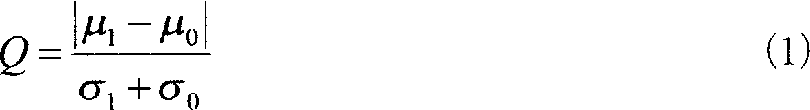
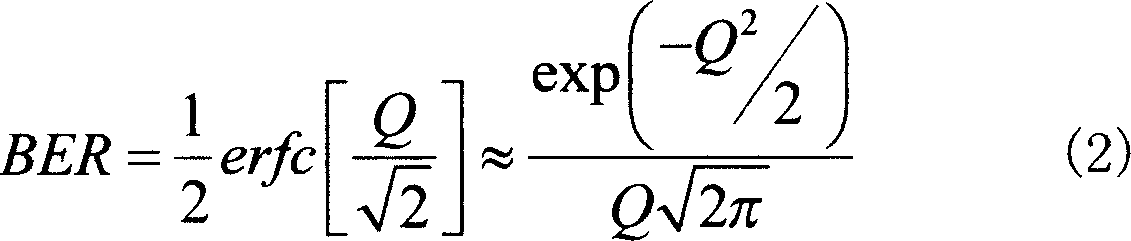
Measuring device and method for quality factor of coherent sampling technical field The present invention relates to a device and method for measuring the quality of an optical signal, which is used in an optical network (optical network) monitoring system to detect the quality factor (quality factor, Q-factor) of the optical signal and evaluate the bit error rate (biterror rate, BER). Background technique Driven by the trend of high-speed optical network / all-optical network, the transmission rate has increased to megabits per second and the transmission distance has become farther and farther. When optical signals are transmitted in channels, there are quite a few factors that will affect the quality of data transmission. Therefore, it is necessary to establish a good optical signal quality monitoring system, so as to effectively manage the optical network and improve performance. However, in addition to the gradual reduction of traditional electricity nodes, the electri...
Claims
Login to View More Application Information
Patent Timeline
 Patent Type & Authority Patents(China)
IPC IPC(8): H04B10/08H04J14/02H04B10/07
Inventor 徐达儒李三良
Owner IND TECH RES INST