Overtuned charging bipole contact device for electric bus

An electrical contact, flip technology, applied in electric vehicles, current collectors, vehicle components, etc., can solve the problems of high maintenance cost, complex structure, short life and other problems, and achieve the effect of avoiding uncontrollable, ensuring safety and simple structure.

Inactive Publication Date: 2007-07-11
马建华
View PDF1 Cites 2 Cited by
  • Summary
  • Abstract
  • Description
  • Claims
  • Application Information

AI Technical Summary

Problems solved by technology

[0004] In order to overcome the disadvantages of the currently used power receiving device, such as complex structure, high failure rate, high maintenance cost, and extremely short life, the present invention provides a flip-type bipolar supercapacitor bus with simple structure and reliable operation. Power receiving contact device

Method used


Image

  • Overtuned charging bipole contact device for electric bus

Examples


Embodiment Construction

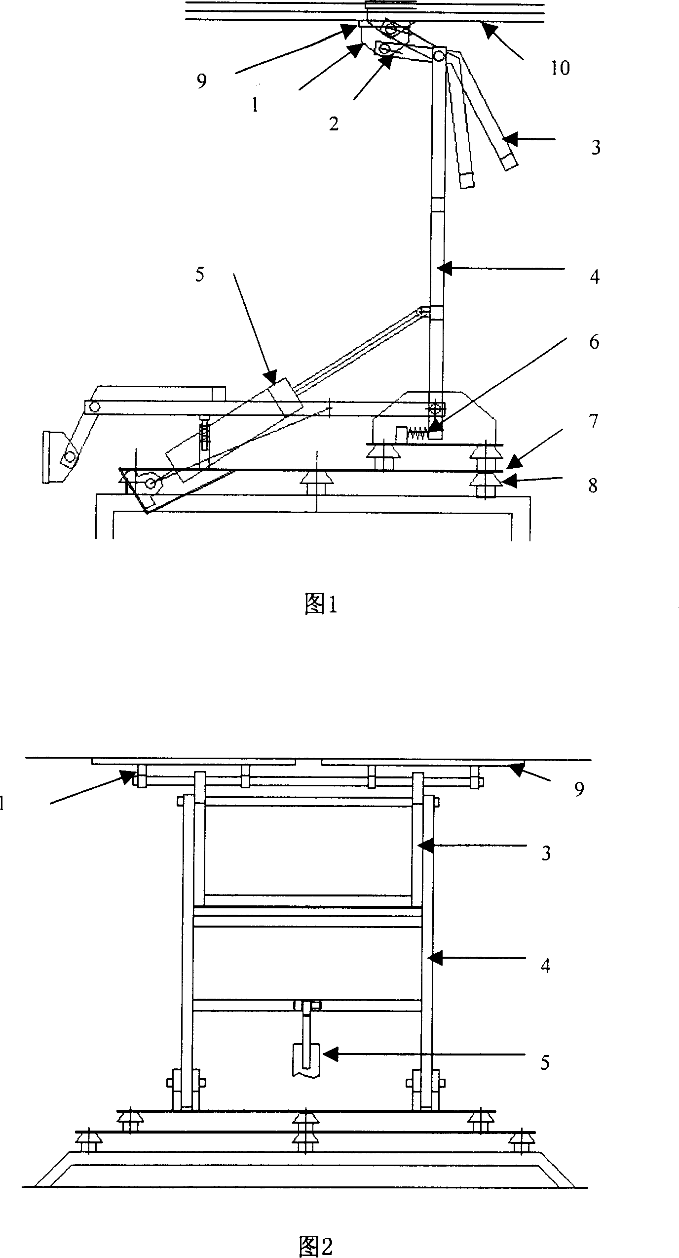
[0009] The present invention will be further described below in conjunction with the accompanying drawings.

[0010] The concrete working principle of the present invention is: utilize the time when the supercapacitor public transport tram enters and unloads passengers, the supercapacitor is charged. The specific action is, firstly, the large flap 4 is pushed by the cylinder 5, and under the action of the buffer spring 6, it is stably erected at the charging position without impact. Forced to tip over under constraints, the size of the tipping moment can be guaranteed by the other side of the small flap 3 and the counterweight, thereby indirectly ensuring that the pressure of the electrode plate 9 on the conductive track 10 is constant and adjustable. That is to ensure that the electrodes are in good contact. After charging finishes, cylinder 5 drives big turnover plate 4 and returns to waiting position. In order to make the power receiving contact 1 adapt to the needs of va...


PUM


Abstract

The invention relates to a bus turnover dual-pole trigger, wherein cylinder pushes the large turnover plate on one chassis and the small turnover plate hinged to the large plate, to drive the trigger and electrode that mounted on the small plate, to contact the fixed conductive track to charge quickly.

Description

technical field [0001] The invention relates to a fast charging device for a supercapacitor bus or other similar equipment / equipment, which belongs to the field of public transportation and related fields. Background technique [0002] Due to the current shortage of oil resources in the world and the improvement of people's awareness of environmental quality, various transportation tools powered by clean energy have gradually entered our lives. One of the buses powered by supercapacitors has started operation or trial operation in several cities in our country. [0003] Through the experience of riding a supercapacitor car and many observations and researches, it is found that there is a certain deficiency in a power receiving device for charging when it is used for parking. Through literature search, it is known that the device is "bus scissor type bipolar pantograph", patent No. CN200410015991.7. From the description disclosed in this patent, it is known that it is a sci...

Claims


Application Information

Patent Timeline
IPC IPC(8): B60L5/16
Inventor 马建华马建新
Owner 马建华
Why Eureka
Try Eureka