
A method for real time detection of the network transfer delay in the RTP

A technology of network transmission and real-time detection, applied in the field of VOIP, can solve the problems of misleading voice codec format, unable to guarantee voice quality requirements, large transmission delay, etc., to improve real-time, conversational voice quality assurance, and ensure accuracy Effect

Active Publication Date: 2007-07-11
ZTE CORP
View PDF0 Cites 27 Cited by
  • Summary
  • Abstract
  • Description
  • Claims
  • Application Information

AI Technical Summary

Problems solved by technology

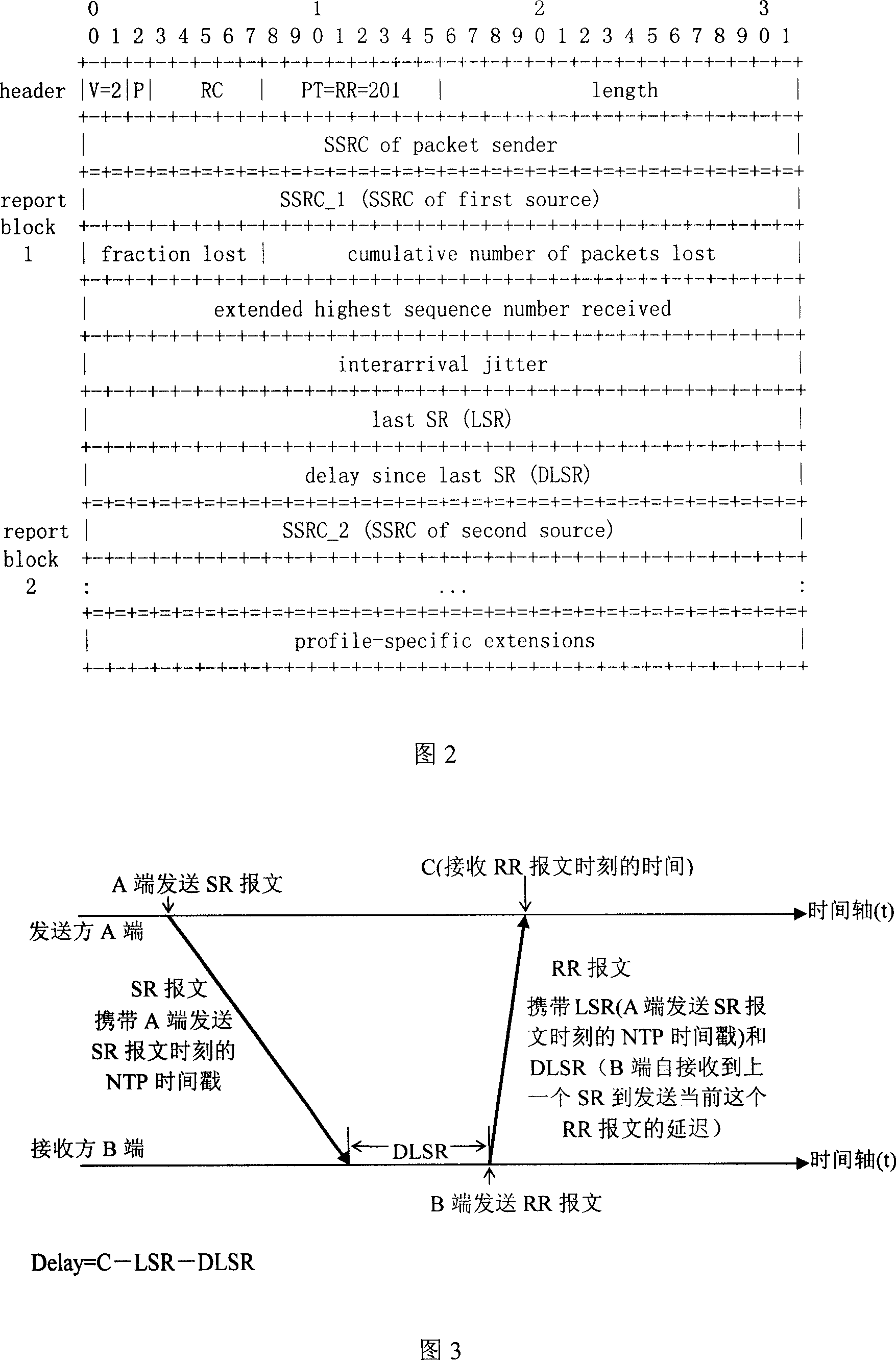
[0007] 1. The NTP time protocol must be enabled to provide accurate clocks for each sender: firstly, the RTP protocol (RFC3550) states that NTP can be disabled; secondly, when NTP is enabled, there must be an accurate time source, which should be the international standard time UTC, The time is propagated by NTP servers. Each sender must be connected to multiple NTP servers to prevent the sender from obtaining accurate time from other servers when the sender cannot contact one of the NTP servers, and to ensure that the clocks of each sender are synchronized. Therefore, enable NTP It will increase the cost and complexity of the system; in addition, once the NTP server is attacked or the time synchronization fails, the calculation result of the network transmission delay will be affected, and the requirements for voice quality cannot be guaranteed
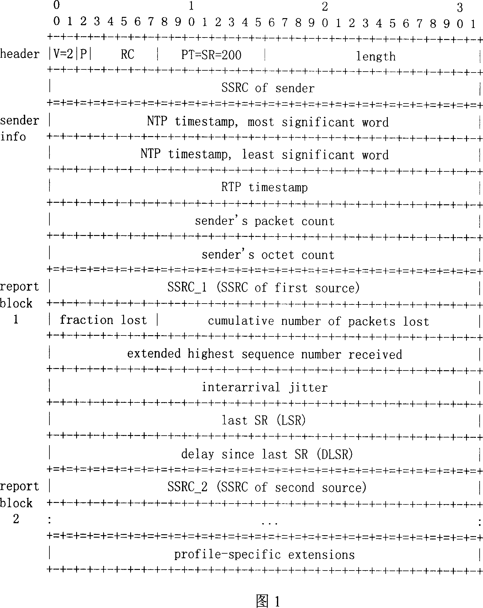
[0008] 2. If the SR message has not been sent, the current network transmission delay cannot be detected: because only the SR message carries the NTP timestamp, the peer end can only obtain the effective LSR and DLSR required to calculate the delay after receiving the SR message
[0009] 3. It can only detect the loopback network transmission delay between the currently received message and the previous sent SR message: if the sender no longer sends the SR message after sending the SR message, that is, during the session It is common for one party to receive other people's voices after sending voice messages for a period of time, and no longer speak. At this time, only the difference between the currently received message and the last SR message can be calculated. If the network transmission delay of the last SR message is large (the network condition is poor), even if the current network condition has improved, the calculated loopback network transmission delay (mainly the last SR message The influence of network transmission delay) is still very large, indicating that the network status is still not ideal, so it cannot accurately reflect the current network status in real time, and may mislead the use of inappropriate voice codec formats, affecting voice quality

Method used


Image

  • A method for real time detection of the network transfer delay in the RTP
  • A method for real time detection of the network transfer delay in the RTP
  • A method for real time detection of the network transfer delay in the RTP

Examples


Embodiment Construction

[0029] For achieving the above object, the method that the present invention adopts is:

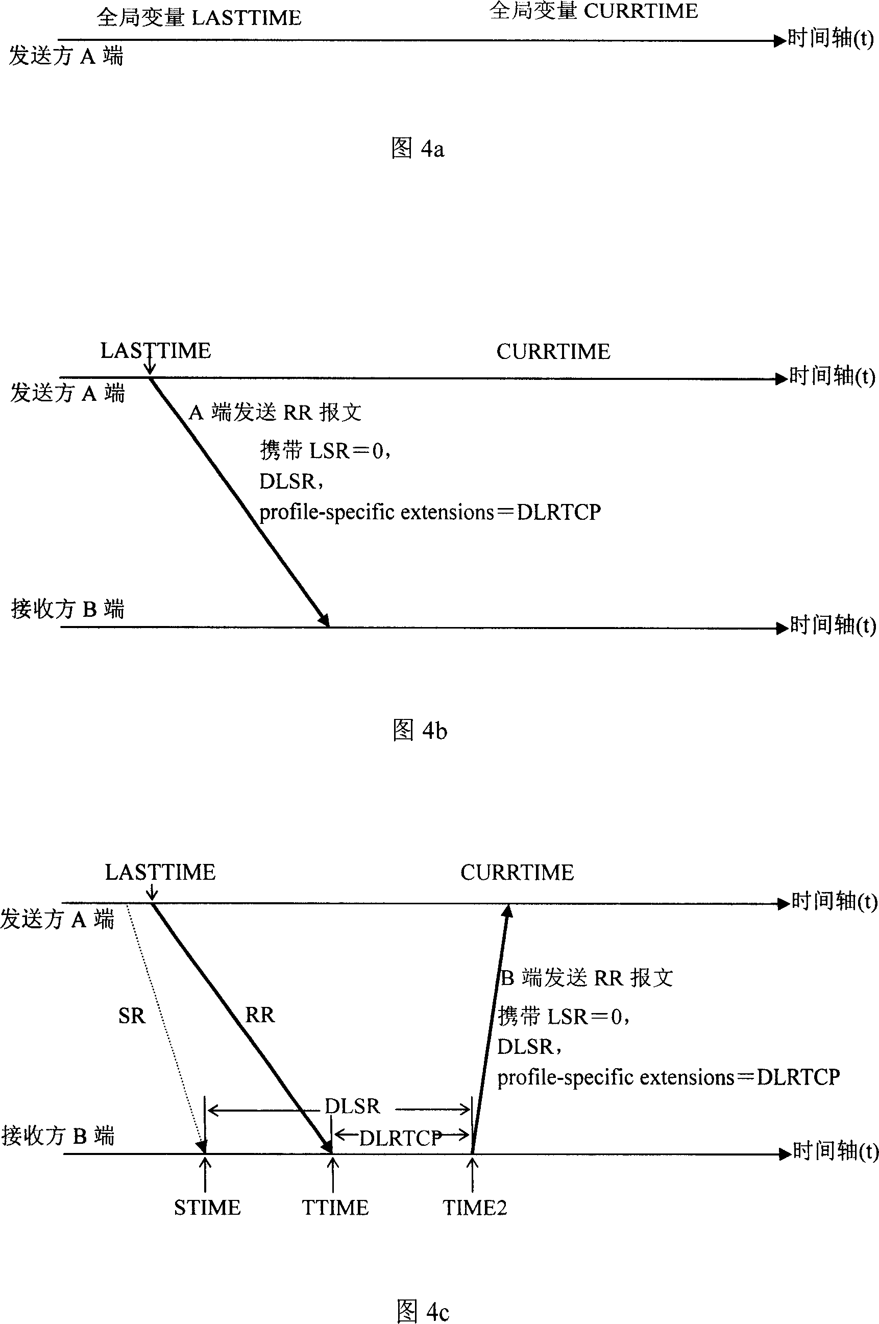
[0030] Record the last system time (LASTTIME) of sending SR / RR and the current system time (CURRTIME) of receiving SR / RR at the local end, and use the peer system time to calculate DLSR (from receiving the last SR to sending the current RR report) message delay) and DLRTCP (the delay from receiving the last SR / RR to sending the current SR / RR message, this item is a custom field, using the extended field profile-specific extensions of the SR / RR message, which is related to DLSR maintains consistency, the unit adopts the same 1 / 65536 second as DLSR), network transmission delay = CURRTIME-LASTTIME-DLRTCP, including the following steps:

[0031] Step 1: Terminal A sets two global variables, LASTTIME and CURRTIME, to respectively record the system time when the local terminal sends SR / RR and receives SR / RR;

[0032] Step 2, end A sends an SR / RR message;

[0033] Step 3: Terminal B records th...


PUM


Abstract

This invention relates to one method to realize real-time test network transmission time lag in RTP, which comprises the following steps: sending SR / RR system time and receiving SR / RR current system time on this end recording; computing network transmission time lag through DLSR and DLRTCP on end system time. This invention determines system time to take place NTP time no matter whether to start NTP agreement without limit of SR messages.

Description

technical field [0001] The invention belongs to the technical field of VOIP, and in particular relates to a method for realizing real-time detection of network transmission delay in RTP (A Transport Protocol for Real-Time Applications), so as to dynamically select voice coding and decoding for services according to network quality. Background technique [0002] RTP provides end-to-end transmission functions for real-time data, such as interactive audio and video data. Functions include payload type identification, serial number encoding, time stamping, and transmission monitoring. RTP is based on the UDP protocol, utilizes UDP multiplexing, and the packet verification function cooperates to complete the transport layer function. [0003] The RTP protocol includes two parts: RTP (for real-time data transmission) and RTCP (for RTP service quality monitoring) session information interaction. The RTP part mainly completes the functions of payload encapsulation, serial number m...

Claims


Application Information

Patent Timeline
Patent Type & Authority Applications(China)
IPC IPC(8): H04L12/26H04L29/06
Inventor 柳海宁张联峰周蕙菁
Owner ZTE CORP
Learn More