Cooling device, and steering bogie and vehicle provided with same
a technology of cooling device and steering bogie, which is applied in the direction of brake cooling, brake arrangement with braking member, braking system, etc., can solve the problems of difficult to radiate heat generated and degrade brake performance, and achieve the effect of maintaining brake performan
- Summary
- Abstract
- Description
- Claims
- Application Information
AI Technical Summary
Benefits of technology
Problems solved by technology
Method used
Image

Examples
first embodiment
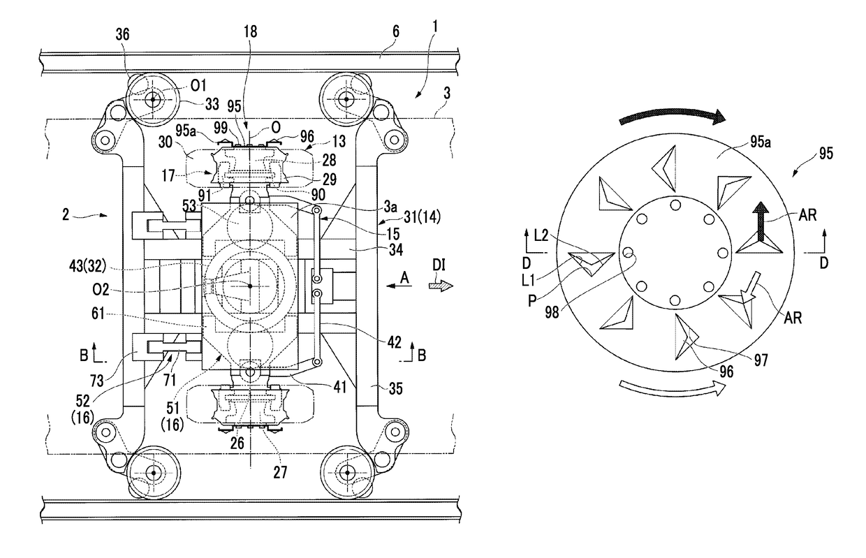
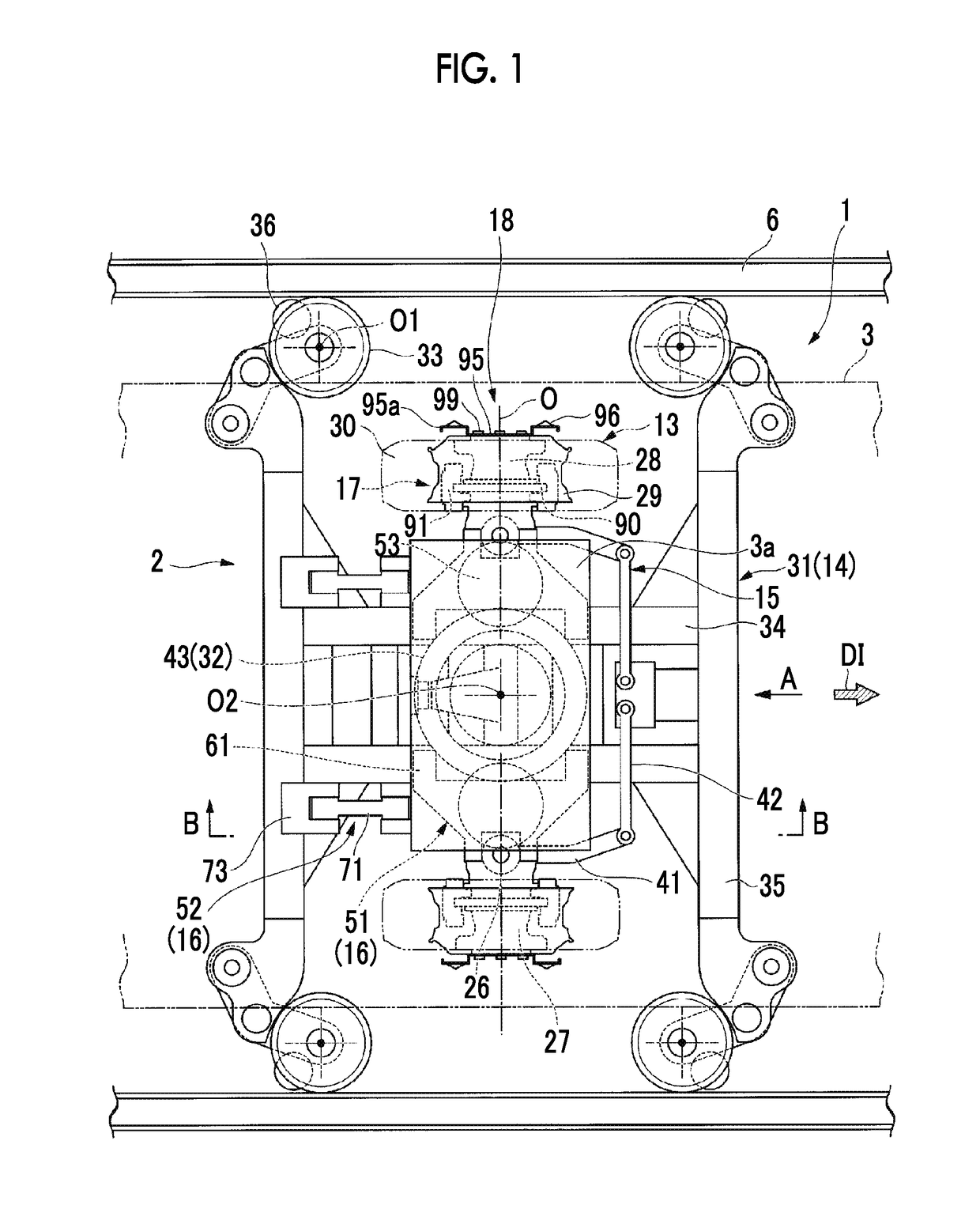
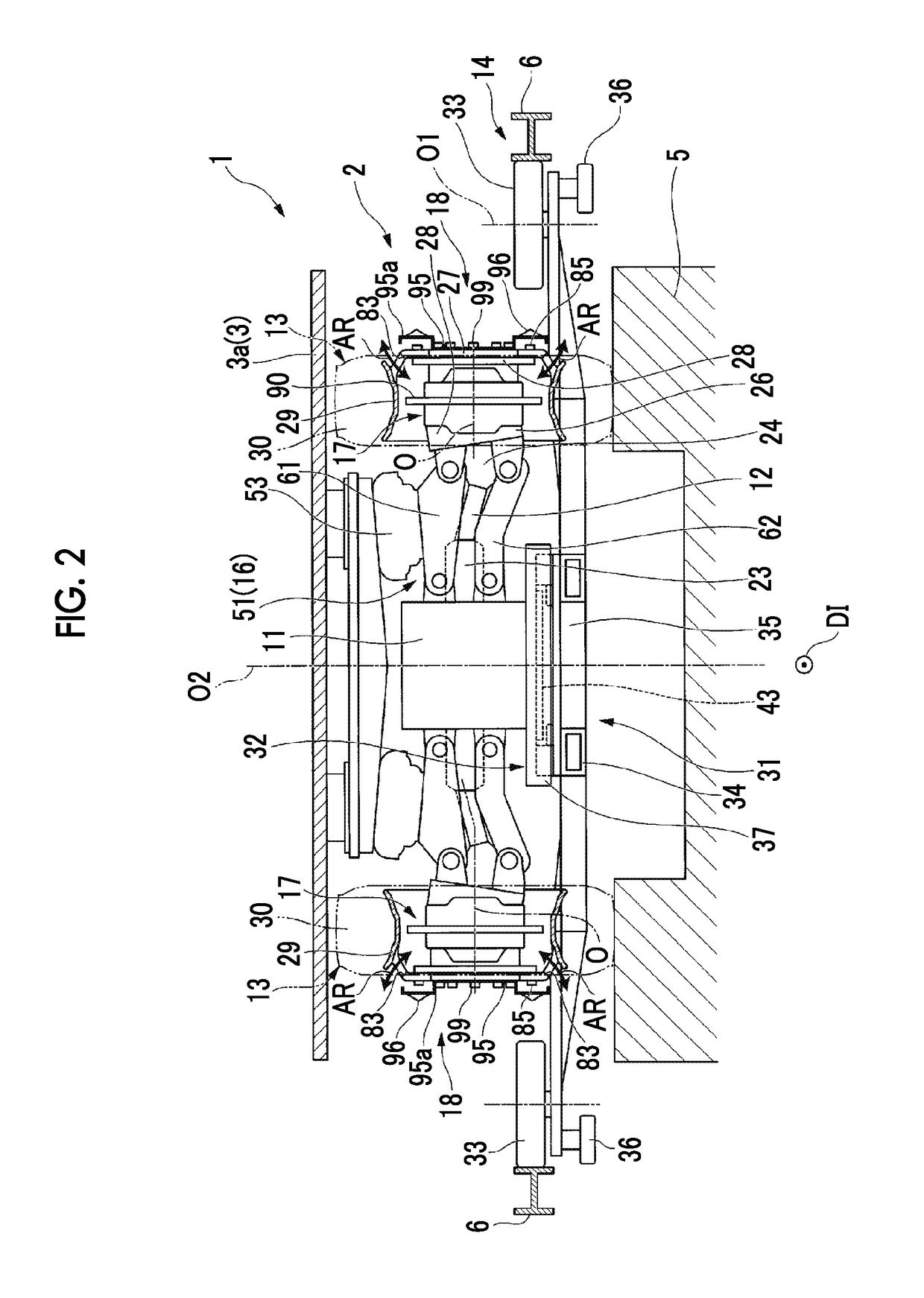
[0054]Hereinafter, a vehicle 1 related to a first embodiment of the invention will be described in detail referring to the drawings.
[0055]As illustrated in FIGS. 1 to 3, the vehicle 1 is a vehicle of a track-based transportation system that travels on a track 5 while being guided by guide rails 6 provided at the track 5. In the present embodiment, the vehicle 1 is a vehicle of a side guide rail type (side guide type) transportation system in which the guide rails 6 extending in an extending direction of the track 5 are provided on both sides of the track 5 in a width direction.
[0056]
[0057]The vehicle 1 includes steering bogies 2 that travel on the track 5, and a car body 3 (refer to FIG. 1) that is supported by the steering bogies 2.
[0058]Directions, such as the front, the rear, the top, the bottom, the left, and the right, in the following description are the same as the directions of the vehicle 1 unless particularly mentioned. Additionally, in the following, a direction of arrow ...
second embodiment
[0127]Next, a vehicle 1A related to a second embodiment of the invention will be described.
[0128]The same constituent elements as those of the first embodiment will be designated by the same reference numerals, and detailed description thereof will be omitted.
[0129]In the vehicle of the present embodiment, a steering bogie 2A is different from that of the first embodiment.
[0130]As illustrated in FIG. 6, the steering bogie 2A includes running wheels 13A of which two are coupled to an end of each axle shaft 12 via the axle hubs 27. That is, the steering bogie 2A with dual tires is used in the present embodiment.
[0131]A running wheel 13A located on the inner side in the width direction among the running wheels 13A coupled to each axle shaft 12 is defined as an inner wheel 13Aa, and a running wheel located on the outer side in the width direction is defined as an outer wheel 13Ab.
[0132]The inner wheel 13Aa has the same configuration as the running wheel 13 of the first embodiment.
[0133]...
third embodiment
[0153]Next, a vehicle 1B related to a third embodiment of the invention will be described.
[0154]In addition, the same constituent elements as those of the first and second embodiments will be designated by the same reference numerals, and detailed description thereof will be omitted.
[0155]The vehicle 1B of the present embodiment is different from the second embodiment in terms of a wind guide member 110 of a steering bogie 2B with the second embodiment as a basic configuration.
[0156]As illustrated in FIG. 8, the wind guide member 110 has a tubular shape that surrounds the openings of the respective decorative holes 83 from an outer peripheral side thereof. The wind guide member 110 is provided so as to be sandwiched between the decorative holes 83 in the inner wheel 13Aa, and the decorative holes 83 in the outer wheel 13Ab, which face each other in the direction of the rotational axis O.
[0157]The same members (not illustrated) as the rubber members 107 are provided at the positions ...
PUM
 Abstract
Description
Claims
Application Information
 - R&D
- Intellectual Property
- Life Sciences
- Materials
- Tech Scout
- Unparalleled Data Quality
- Higher Quality Content
- 60% Fewer Hallucinations
Browse by: Latest US Patents, China's latest patents, Technical Efficacy Thesaurus, Application Domain, Technology Topic, Popular Technical Reports.
© 2025 PatSnap. All rights reserved.Legal|Privacy policy|Modern Slavery Act Transparency Statement|Sitemap|About US| Contact US: help@patsnap.com