
MEMS microphone

a microphone and microphone technology, applied in the field of mems microphones, can solve the problems of poor environment, severe impact on yield, and inability to work correctly with mems microphones, and achieve the effect of reducing the probability of adhesion and highest mechanical sensitivity

Active Publication Date: 2018-06-19
CSMC TECH FAB2 CO LTD
View PDF16 Cites 0 Cited by
  • Summary
  • Abstract
  • Description
  • Claims
  • Application Information

AI Technical Summary

Benefits of technology

[0005]Accordingly, it is necessary to provide a MEMS microphone which can effectively reduce a probability of an adhesion generated between a vibrating diaphragm and a backplate, and improve a yield.
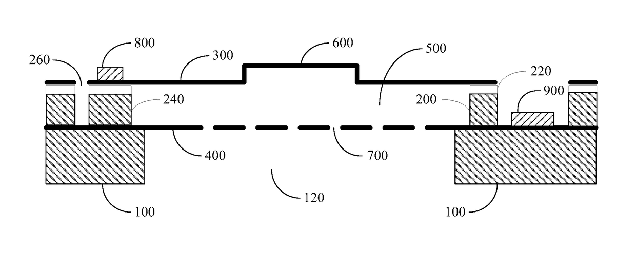
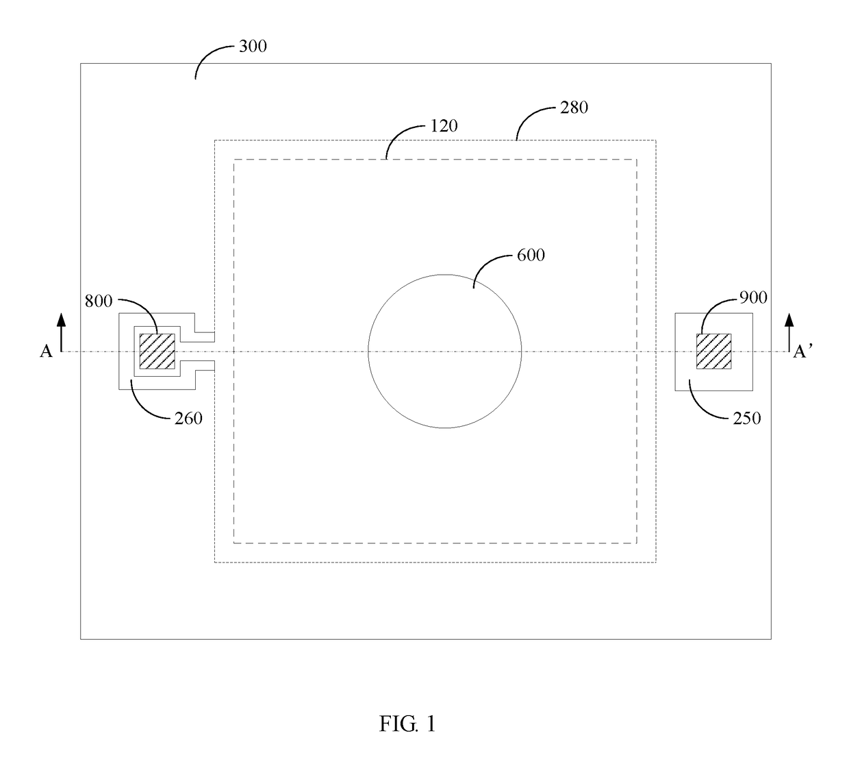
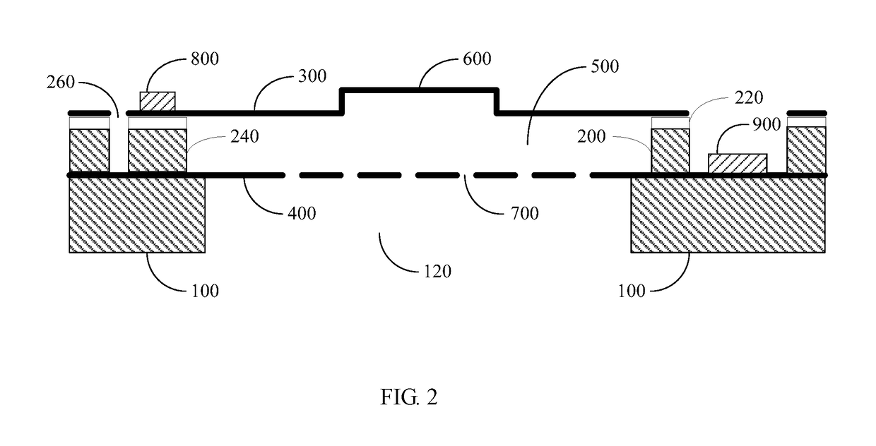
[0007]In the above MEMS microphone, because the central region of the upper polar plate or the central region of the lower polar plate is provided with a recess, a distance between the central region of upper polar plate and the central region of the lower polar plate is relatively far, the upper polar plate (for example serving as the vibrating diaphragm) and the lower polar plate (for example serving as the backplate) which form a variable capacitance structure are difficult to be adhered to each other, thus effectively reducing a probability of an adhesion generated between the vibrating diaphragm and the backplate, and improving a yield. At the same time, because it is not necessary to remove the central region of the polar plate of the variable capacitance, it effectively takes advantage of the region of the vibrating diaphragm having a highest mechanical sensitivity, and the sensitivity of the MEMS microphone is maintained to the maximum extent.

Problems solved by technology

In addition, the capacitive MEMS microphone has a wide working temperature, it can work under a poor environment.
However, the softer of the vibrating diaphragm, the easier it is adhered to the backplate, causing the MEMS microphone not to work correctly, and a yield is severely affected.
There are various methods to avoid the adhesion between the backplate and the vibrating diaphragm, at present, a more efficient method is to produce anti-adhesion bulges, however, the process steps are increased, and a cost is increased.
However, the central region of the vibrating diaphragm has the highest mechanical sensitivity, and the edges have a lower mechanical sensitivity, when the central region of the backplate is excavated, the central position of the vibrating diaphragm is wasted, reducing a sensitivity of the MEMS microphone

Method used


Image

  • MEMS microphone
  • MEMS microphone
  • MEMS microphone

Examples


Embodiment Construction

[0013]Embodiments of the invention are described more fully hereinafter with reference to the accompanying drawings. The various embodiments of the invention may, however, be embodied in many different forms and should not be construed as limited to the embodiments set forth herein. Rather, these embodiments are provided so that this disclosure will be thorough and complete, and will fully convey the scope of the invention to those skilled in the art. Elements that are identified using the same or similar reference characters refer to the same or similar elements.

[0014]Unless otherwise defined, all terms (including technical and scientific terms) used herein have the same meaning as commonly understood by one of ordinary skill in the art to which this invention belongs. It will be further understood that terms, such as those defined in commonly used dictionaries, should be interpreted as having a meaning that is consistent with their meaning in the context of the relevant art and wi...


PUM


Abstract

A MEMS microphone includes a substrate (100), a supporting part (200), an upper polar plate (300) and a lower polar plate (400). The substrate (100) is provided with an opening (120) penetrating the middle thereof; the lower polar plate (400) straddles the opening (120); the supporting part (200) is fixed on the lower polar plate (400); the upper polar plate (300) is affixed to the supporting part (200); an accommodating cavity (500) is formed among the supporting part (200), the upper polar plate (300) and the lower polar plate (400); a recess (600) opposite to the accommodating cavity (500) is arranged in an intermediate region of at least one of the upper polar plate (300) and the lower polar plate (400), and insulation is achieved between the upper polar plate (300) and a lower polar plate (400).

Description

FIELD OF THE INVENTION[0001]The present invention relates to a technical field of semiconductor devices, and more particular relates to a MEMS microphone.BACKGROUND OF THE INVENTION[0002]The research of MEMS microphone chip has been continued for about 20 years, during this time, various microphone chips have been developed, such as piezo-resistive chip, piezo-electric chip, and capacitive microphones chip, in which the application of the capacitive MEMS microphone is most extensively. The capacitive MEMS microphone possesses advantages as follows: such as a mall volume, a high sensitivity, a better frequency characteristic, and a low noise. In addition, the capacitive MEMS microphone has a wide working temperature, it can work under a poor environment. The capacitive microphone can be distinguished into a double diaphragm capacitive structure and a signal diaphragm capacitive structure, and most of the capacitive microphones in which adopts the double diaphragm capacitive structure...

Claims


Application Information

Patent Timeline
Patent Type & Authority Patents(United States)
IPC IPC(8): H04R19/04H04R7/12H04R7/14B81B3/00H04R7/16
CPCH04R19/04B81B3/0037H04R7/12H04R7/14H04R7/16B81B2201/0257B81B2203/0127B81B2203/0315H04R2201/003H04R19/005G01L9/0045G01L9/0073
Inventor HU, YONGGANG
Owner CSMC TECH FAB2 CO LTD
Learn More