Control of a gas turbine engine

a gas turbine engine and control technology, applied in the direction of machines/engines, sustainable transportation, mechanical equipment, etc., can solve the problems of reducing the maximum power output capability of the engine, increasing the operating temperature, and placing a practical limit on the power output availabl

Active Publication Date: 2018-06-26
ROLLS ROYCE PLC
View PDF14 Cites 1 Cited by
  • Summary
  • Abstract
  • Description
  • Claims
  • Application Information

AI Technical Summary

Benefits of technology

[0012]biasing the scheduling of the angle variation of the variable stator vanes as a function of the operational parameter(s) to reduce variation in temperature at entry to the core turbine.
[0013]The present invention is at least partly based on a realisation that an engine architecture with VSVs on a booster compressor which is constrained to run in a fixed speed relationship to an external load has the property that the relationship between core flow and temperature can be controlled by manipulation of the VSVs. This is because changing the VSV angle controls the amount of work done by the booster compressor, whilst its speed, which is set by the characteristics of the external load, remains fixed. For example, if the VSVs are opened the angle of incidence on the rotors increases and therefore more work is done by the booster compressor. Its pressure ratio will therefore increase and in doing so it will drive more flow into the core. If the turbine temperature is maintained constant at the same time as opening the VSVs by regulating fuel flow, the power output from the engine will increase.
[0014]Put another way, in a conventional engine in which each compressor is powered by an independent turbine, it is the speed characteristic of the compressor on each spool which dictates the rotational speed of that spool at each operating point. By speed characteristic is meant the variation of compressor aero work with speed. This is because the work output of a turbine is substantially invariant with speed. For a given spool power, there are many different turbine speeds but only one compressor speed at which conservation of energy may be satisfied. The compressor workspeed relationship therefore sets the speed of the spool. For example, in the case of a conventional turbofan aero engine it is the speed characteristic of the fan (the external load) which dictates the speed of the low pressure spool at each operating point, and in the case of a gas turbine with a free power turbine powering an external load (e.g. electricity generation) it is the speed characteristic of the load which dictates the speed of the free power turbine. However, according to the present invention, the speed characteristic of the external load dictates the speed of the low-pressure spool, and hence the speed of the low pressure turbine and the booster compressor. Articulation of the VSVs therefore allows the amount of work done by the booster compressor to be controlled whilst its speed, which is set by the external load, remains fixed.
[0017]Satisfy the maximum power output requirement using a smaller engine or one of reduced temperature capability, relative to a conventional engine. The engine can be more efficient during normal operation when the power output is reduced (e.g. at cruise in an aeroengine).
[0033]According to another option, the operational parameters include a different indirect measure of the temperature at entry to the core turbine. For example, the operational parameters can include a measure of the temperature at entry to the low-pressure turbine. The operational parameters may further include a measure of the temperature of the air exiting the core compressor. By using both parameters, the scheduling bias can be defined in such a way as to minimise or reduce the consumption of turbine life at all operating conditions. Indeed, the method may further include calculating an error between the (indirectly) measured temperature at entry to the core turbine and a desired temperature at entry to the core turbine at the measured temperature of the air exiting the core compressor, the scheduling of the angle variation of the VSVs being biased as a function of the calculated error. For example, the calculated error can be an input into a closed loop (e.g. PID) controller which determines the scheduling bias in order to reduce the error while maintaining a constant engine power output.
[0035]The gas turbine engine may be a turbofan, the external load then being a propulsive fan. Such a fan typically has a defined speed characteristic in which its speed varies in a predetermined fashion relative to the power produced by the low-pressure turbine. In particular, the turbofan may be a geared turbofan, the propulsive fan being operatively connected to the low-pressure shaft via a gearbox. Controlling the relationship between core flow and temperature by manipulation of the VSVs of a geared turbofan can be especially effective because in such an engine the booster compressor typically provides a relatively high pressure ratio, and thus varying the angle of the VSVs can have a correspondingly important effect on the core flow versus temperature relationship.

Problems solved by technology

For an engine of fixed physical size and pressure ratio (and hence core flow) the temperature capability of the engine therefore places a practical limit on the power output available from it.
Firstly, the engine must be physically sized and the temperature capability of the components designed for the most arduous operating conditions (i.e. maximum power output requirement).
Secondly, as the engine deteriorates over time, its operating temperatures increase due to the reduction in component efficiencies.
The maximum power output capability of the engine therefore reduces until it is no longer able to supply the required power.

Method used


Image

  • Control of a gas turbine engine
  • Control of a gas turbine engine
  • Control of a gas turbine engine

Examples


Embodiment Construction

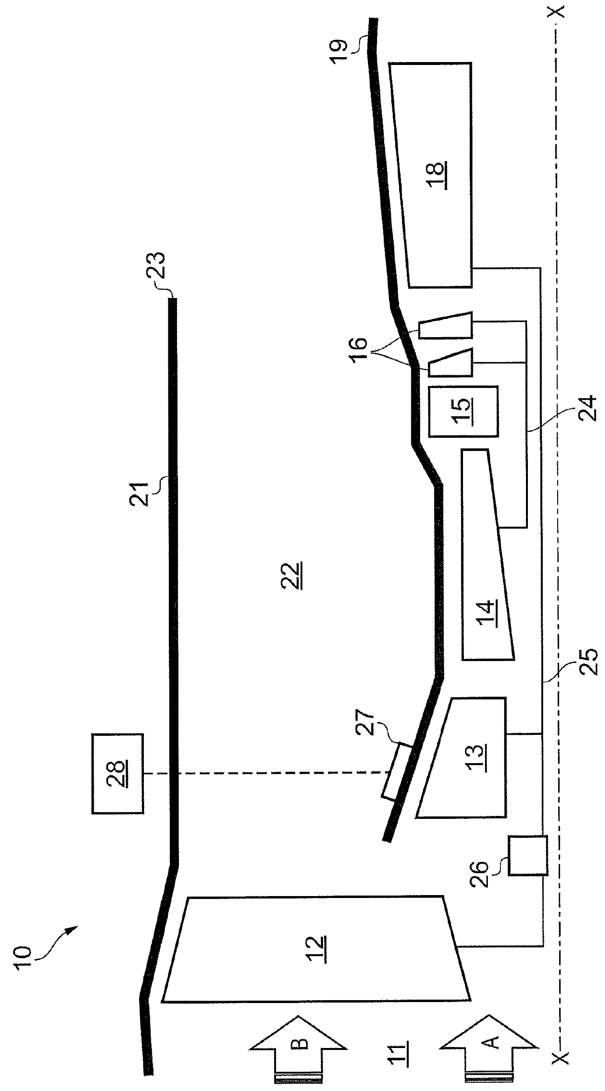
[0049]With reference to FIG. 2, a geared, ducted fan gas turbine engine incorporating the invention is generally indicated at 10 and has a principal and rotational axis X-X. The engine comprises, in axial flow series, an air intake 11, a propulsive fan 12, a booster compressor 13, a core compressor 14, combustion equipment 15, a core turbine 16, a low-pressure turbine 18 and a core engine exhaust nozzle 19. A nacelle 21 generally surrounds the engine 10 and defines the intake 11, a bypass duct 22 and a bypass exhaust nozzle 23.

[0050]During operation, air entering the intake 11 is accelerated by the fan 12 to produce two air flows: a first air flow A into the booster compressor 13 and a second air flow B which passes through the bypass duct 22 to provide propulsive thrust. The booster compressor 13 compresses the air flow A directed into it before delivering that air to the core compressor 14 where further compression takes place.

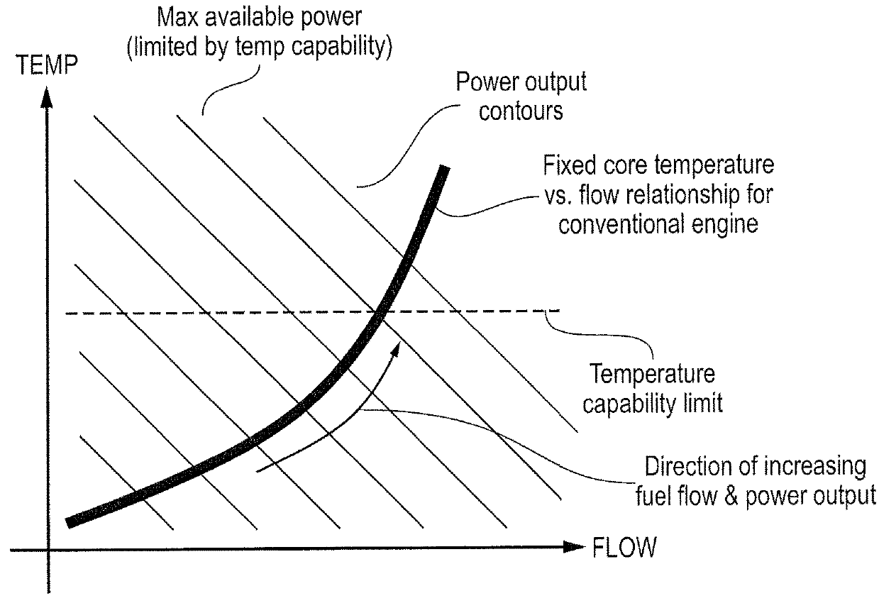
[0051]The compressed air exhausted from the core compr...


PUM


Abstract

An engine that has, in axial flow series, booster compressor, core compressor, combustion equipment, core turbine, and low-pressure turbine. Core turbine drives core compressor via an interconnecting high-pressure shaft. Low-pressure turbine drives booster compressor via an interconnecting low-pressure shaft. Low-pressure turbine also drives external load having a defined speed characteristic that dictates speed of the low-pressure turbine and booster compressor. Booster compressor has one or more rows of variable stator vanes. The method includes: scheduling variation in the angle of variable stator vanes as a function of speed of the booster compressor wherein the vanes open as booster compressor speed increases; measuring or setting one or more operational parameters which are determinative of temperature at entry to core turbine; and biasing scheduling of angle variation of variable stator vanes as a function of operational parameter(s) to reduce variation in temperature at entry to core turbine.

Description

FIELD OF THE INVENTION[0001]The present invention relates to control of a gas turbine engine.BACKGROUND OF THE INVENTION[0002]The power output from a gas turbine engine is directly proportional to both the temperature at which it operates and the quantity of air that flows through it. For a conventional gas turbine engine in which each compressor is powered by an independent turbine, the relationship between core flow and temperatures is fixed. In order to increase the power output from the engine more fuel must be burned in the combustor. This increases both core flow and temperatures. The operating temperatures of the engine must be closely monitored and the fuel supply regulated to prevent the temperature capability of the engine being exceeded. For an engine of fixed physical size and pressure ratio (and hence core flow) the temperature capability of the engine therefore places a practical limit on the power output available from it.[0003]This is illustrated in FIG. 1 which show...

Claims


Application Information

Patent Timeline
Patent Type & Authority Patents(United States)
IPC IPC(8): F02C9/22F01D17/16F02C9/20F02C9/54F02C6/00F02C7/36
CPCF02C9/22F01D17/162F02C6/00F02C7/36F02C9/20F02C9/54Y02T50/671F05D2220/76F05D2270/05F05D2270/06F05D2270/303F05D2270/304F05D2220/32Y02T50/60
Inventor GARDNER, ALASDAIRROWE, ARTHUR LAURENCETAYLOR, MARK DAVIDHOWARTH, NICHOLAS
Owner ROLLS ROYCE PLC
Why Eureka
Try Eureka