
Injector, in particular an injector for gaseous fuels

a gaseous fuel and injector technology, applied in the field of injectors, can solve the problems of limited temperature resistance, wear resistance, and use, and achieve the effects of reducing noise development and wear, reducing force spikes, and reducing the effect of force spikes

Active Publication Date: 2018-07-03
ROBERT BOSCH GMBH
View PDF9 Cites 1 Cited by
  • Summary
  • Abstract
  • Description
  • Claims
  • Application Information

AI Technical Summary

Benefits of technology

This design enhances the service life and tightness of the injector, reducing wear and noise while maintaining effective sealing for gaseous fuels, making it suitable for direct injection into combustion chambers.

Problems solved by technology

However, the known injectors for liquid fuels are only conditionally suitable for such gaseous fuels, since gaseous fuels have different energy densities and volumes than liquid fuels.
However, one problem inherent in such elastomeric seals is their limited temperature resistance and their susceptibility to wear, which prevents their use especially in the direct injection of gaseous fuel into a combustion chamber, because the temperatures at the valve tip are too high.
These two sealing partners ensure sufficient tightness for liquid fuels even for very high numbers of switching cycles, but problems arise with gaseous fuels because of the high wear of the valve seat that occurs.
This is attributable to the lack of hydraulic damping, which is present when liquid fuel is involved.
In the case of gaseous fuels, however, the repeated impacts of a tappet or the like on the valve seat leads to increased wear and undesired noise.

Method used


Image

  • Injector, in particular an injector for gaseous fuels
  • Injector, in particular an injector for gaseous fuels
  • Injector, in particular an injector for gaseous fuels

Examples


Embodiment Construction

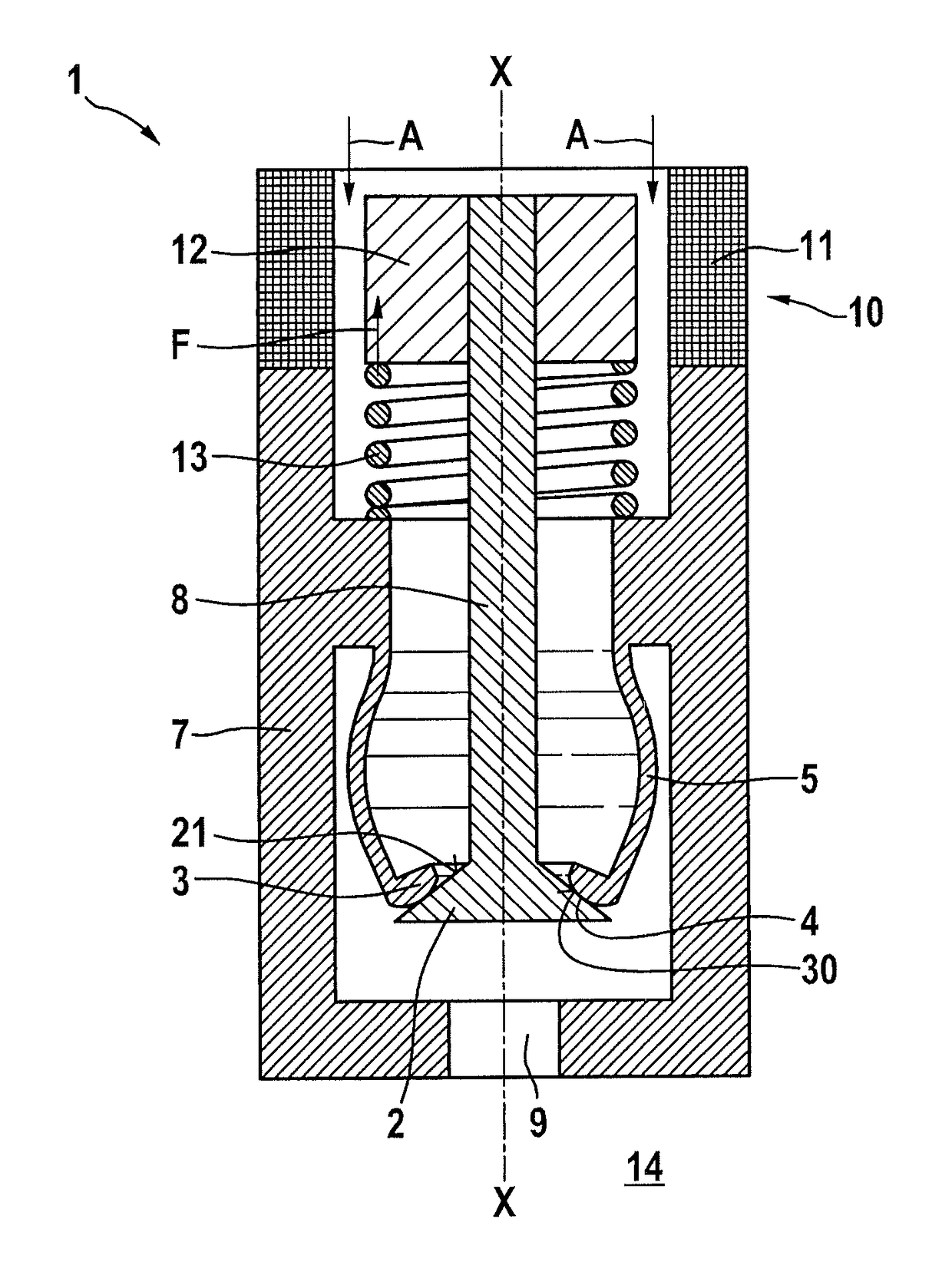
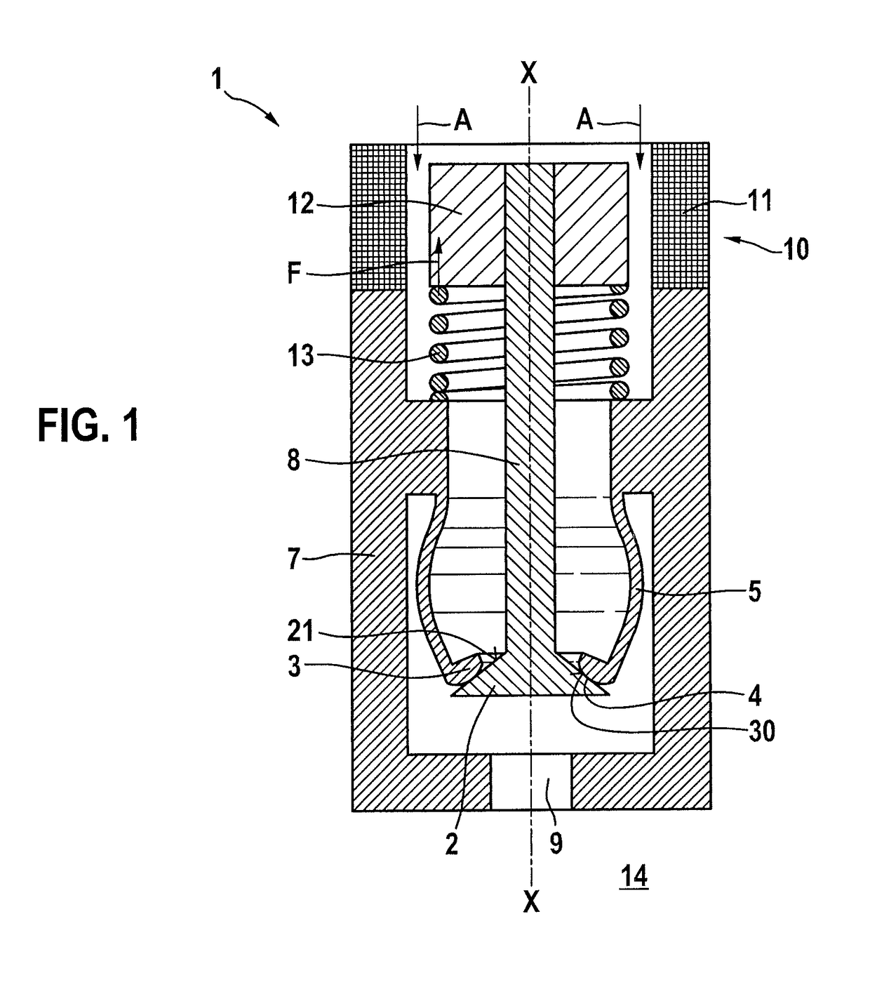
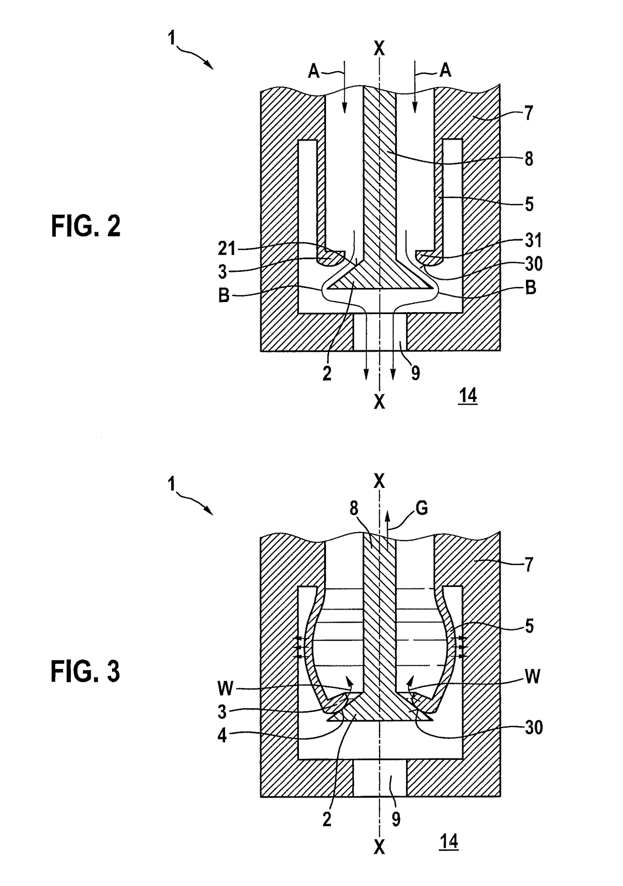
[0019]In the following text, an injector 1 according to a first exemplary embodiment of the present invention is described in detail with reference to FIGS. 1 through 3.

[0020]FIG. 1 schematically illustrates the structure of injector 1, which is a blow-in injector in this exemplary embodiment, which injects directly into a combustion chamber 14. Injector 1 includes a first sealing element 2 and a second sealing element 3. FIG. 1 shows the closed state of injector 1. A first sealing region 4 is configured between the two sealing elements 2, 3. In addition, an elastic deformation region 5 is provided on second sealing element 3, separately from sealing region 4.

[0021]First sealing element 2 is configured in one piece with a valve needle 8 and has a tapering sealing surface 21. Sealing surface 21 may be conical. Second sealing element 3 is cylindrical in the relaxed state (FIG. 2). At its radially inwardly directed region second sealing element 3 is provided with an annular flange 31. ...


PUM


Abstract

An injector, in particular a blow-in injector for gaseous fuel, including a first sealing element and a second sealing element, and in the closed state of the injector a first sealing region is configured between the first and second sealing element, at least one of the sealing elements having an elastic deformation region, the elastic deformation region being set apart from the sealing region between the first and second sealing element.

Description

RELATED APPLICATION INFORMATION[0001]The present application claims priority to and the benefit of German patent application no. 10 2014 212 339.9, which was filed in Germany on Jun. 26, 2014, the disclosure of which is incorporated herein by reference.FIELD OF THE INVENTION[0002]The present invention relates to an injector and in particular to a blow-in injector for gaseous fuels.BACKGROUND INFORMATION[0003]In addition to conventionally used liquid fuels, the use of gaseous fuels such as natural gas or hydrogen has increased over the past few years. However, the known injectors for liquid fuels are only conditionally suitable for such gaseous fuels, since gaseous fuels have different energy densities and volumes than liquid fuels. To ensure that internal combustion engines operated in this manner do not consume excessive fuel, it is necessary to inject the most precise gas quantities possible in each injection. The injector must also provide sufficient tightness between the individ...

Claims


Application Information

Patent Timeline
Patent Type & Authority Patents(United States)
IPC IPC(8): F02M21/02
CPCF02M21/0269Y02T10/32F02M21/0275F02M21/0254Y02T10/30
Inventor SCHMIEDER, DIETMARMUELLER, MARTINKRISSLER, SVENSCHOENROCK, OLAFKUCKERT, HAGENVOGT, ANDREAS
Owner ROBERT BOSCH GMBH
Learn More