Pressure wave supercharger

a supercharger and current pressure wave technology, applied in the direction of machines/engines, non-positive displacement fluid engines, pump installations, etc., can solve the problems of adversely affecting the efficiency of the pressure wave supercharger, current pressure wave superchargers encounter problems, etc., to achieve rapid heat up, reduce the effect of heat energy consumption

Inactive Publication Date: 2012-02-16
BENTELER AUTOMOBILTECHNIK GMBH
View PDF6 Cites 1 Cited by
  • Summary
  • Abstract
  • Description
  • Claims
  • Application Information

AI Technical Summary

Benefits of technology

[0016]According to another advantageous feature of the present invention, an insulation jacket is provided to surround the rotor casing. The insulation jacket assumes hereby the function to additionally thermally insulate the rotor casing against the surroundings. Heat dissipation through convection or heat radiation across the surface of the rotor casing is further minimized by the insulation jacket. As a result, only a minor part of heat is emitted from the rotor casing to the surroundings, in particular during the heat-up phase of the pressure wave supercharger. Thus, the rotor casing heats up faster and reaches an optimal operating temperature which is best suited to the rotor and allows the formation of an optimum gap size between rotor and rotor casing.
[0017]According to another advantageous feature of the present invention, the insulation jacket has an inner side and an outer side, with the inner and outer sides of the insulation jacket having a surface roughness which can be made smaller than a surface roughness of the inner surface of the rotor casing. The term “surface roughness” again relates to a rolled smooth surface which is as reflective as possible for reflection of heat radiation. The inner side of the insulation jacket reflects back heat emitted from the rotor casing so that the rotor casing is able to more rapidly heat up, in particular during the warmup phase.
[0018]The reflective or metallically smooth surface on the outer side of the insulation jacket has the same effect as the surface condition on the outer side of the rotor casing. Heat energy contained in the insulation jacket is prevented on the outer side of the insulation jacket to dissipate from the insulation jacket in the form of heat radiation. As a result, there is a smaller temperature gradient in the insulation jacket so that less heat is emitted from the rotor casing via the insulation jacket to the surroundings.
[0019]According to another advantageous feature of the present invention, the insulation jacket and the rotor casing can define an air gap there between. The air gap provides an additional insulation layer between the outer side of the rotor casing and the inner side of the insulation jacket in view of the small heat conductivity of air. This promotes a more rapid heat-up of the rotor casing.
[0020]According to another advantageous feature of the present invention, the insulation jacket may be made of a metallic material. The components of the pressure wave supercharger heat up to a maximum temperature of about 100° C. to 400° C. whereas the hot gases conveyed by the exhaust into the pressure wave supercharger have a temperature of up to 1100° C., and the immediate surroundings of the internal combustion engine lies in a temperature range of about 70° C. to 130° C. operating temperature. The metallic material of the insulation jacket has thus a particular positive effect on the service life of the insulation jacket.
[0021]According to another advantageous feature of the present invention, the rotor casing is made of a material defined by a thermal expansion coefficient which can be greater than or equal to a thermal expansion coefficient of a material of the rotor. As the components are exposed to heat energy, they undergo a thermal expansion. In view of their different configuration and different contact intensity with hot gas, the expansion of the various components is antiproportional in relation to one another. When the thermal expansion coefficient of the rotor casing is equal to or greater than the thermal expansion coefficient of the rotor, the risk of seizing of the rotor in the rotor casing is eliminated even when the gap size between rotor and rotor casing is minimal. The at least same or greater thermal expansion coefficient of the rotor casing promotes a faster expansion of the rotor casing in the warm-up phase in relation to the rotor so that a previously calculated optimum gap can be established between rotor and rotor casing during normal operation.

Problems solved by technology

Current pressure wave superchargers encounter problems as a result of thermal stress to which all components of the cell rotor are exposed.
Temperatures of up to 1100° C. can be experienced on the hot side of the cell rotor whereas the cold side is subject to a temperature of maximal 200° C. A warping, caused by heat, may be encountered, adversely affecting the efficiency of the pressure wave supercharger.

Method used


Image

  • Pressure wave supercharger
  • Pressure wave supercharger

Examples


Embodiment Construction

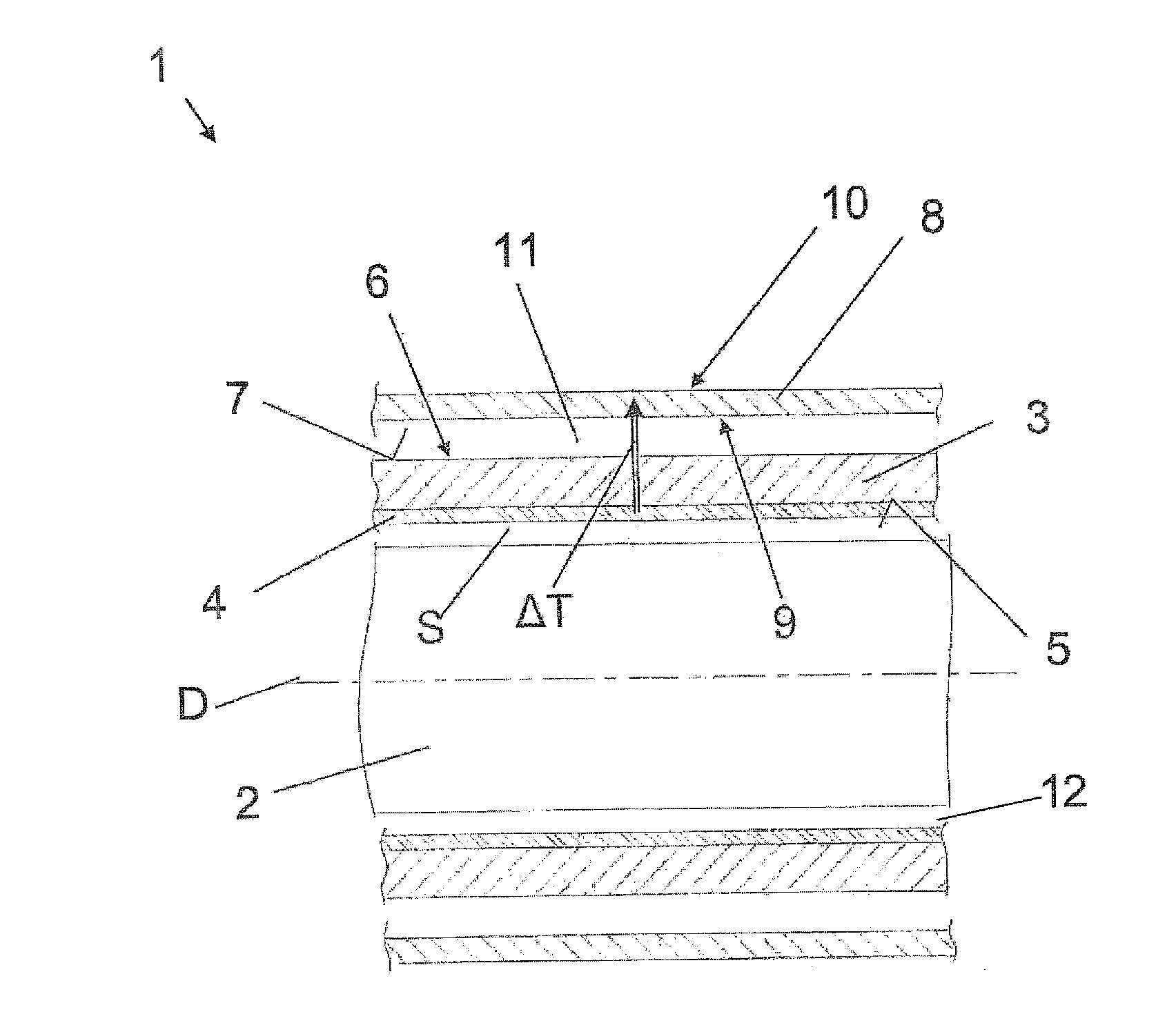
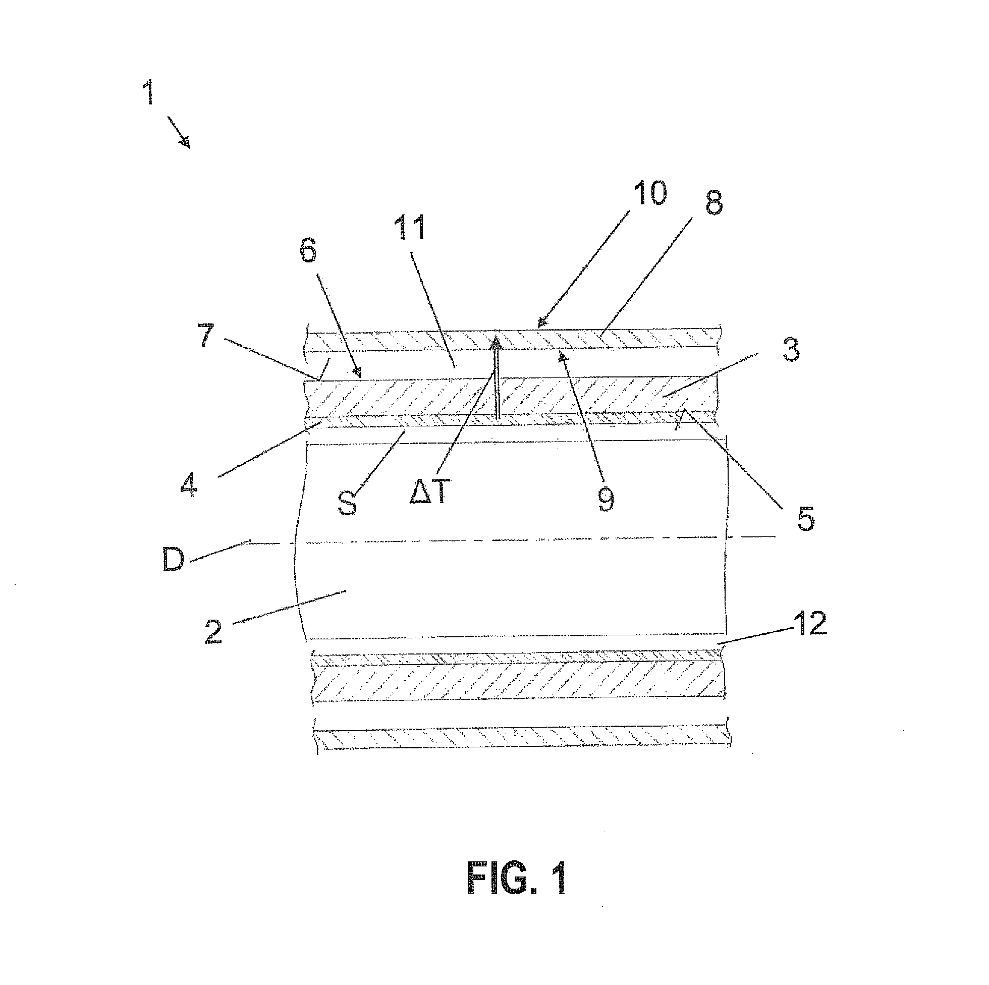
[0023]The depicted embodiment is to be understood as illustrative of the invention and not as limiting in any way. It should also be understood that the figure is not necessarily to scale. In certain instances, details which are not necessary for an understanding of the present invention or which render other details difficult to perceive may have been omitted.

[0024]Turning now to FIG. 1, there is shown a simplified sectional cutaway view of a pressure wave supercharger according to the present invention, generally designated by reference numeral 1. The pressure wave supercharger 1 includes an internal rotor 2 and a rotor casing 3 in surrounding relationship to the rotor 2. At operation, the rotor 2 rotates rotationally-symmetrical about a rotation axis D. The rotor casing 3 is securely fixed to an internal combustion engine (not shown). Provided between the rotor 2 and the rotor casing 3 is a gap 12 which can be dimensioned in accordance with the present invention as minimally as p...


PUM


Abstract

A pressure wave supercharger for installation on an internal combustion engine of a motor vehicle includes a rotor casing having an inner surface, and a rotor received in the rotor casing. A coating is applied on the inner surface of the rotor casing for absorbing heat radiation. The rotor casing is surrounded by an insulation jacket.

Description

CROSS-REFERENCES TO RELATED APPLICATIONS[0001]This application claims the priority of German Patent Application, Serial No. 10 2010 008 386.0-13, filed Feb. 17, 2010, pursuant to 35 U.S.C. 119(a)-(d), the content of which is incorporated herein by reference in its entirety as if fully set forth herein.BACKGROUND OF THE INVENTION[0002]The present invention relates to a pressure wave supercharger for installation on an internal combustion engine of a motor vehicle.[0003]The following discussion of related art is provided to assist the reader in understanding the advantages of the invention, and is not to be construed as an admission that this related art is prior art to this invention.[0004]Internal combustion engines for motor vehicles are supercharged to increase efficiency. The gas exchange is improved during the intake cycle through increase of the charging degree of the cylinder. Supercharged engines consume less fuel compared to engines that are not charged. A supercharged motor...

Claims


Application Information

Patent Timeline
Patent Type & Authority Applications(United States)
IPC IPC(8): F02B33/40F04D25/00
CPCF04F13/00
Inventor GLITZ, GEORGARASZKIEWICZ, JAN
Owner BENTELER AUTOMOBILTECHNIK GMBH
Why Eureka
Try Eureka