Heat dissipating device

a heat dissipating device and heat dissipation technology, which is applied in the direction of lighting and heating apparatus, cooling/ventilation/heating modifications, basic electric elements, etc., can solve the problems of heat resistance, difficulty in dissipating heat, and thicker heat boundary layer depth, so as to reduce the total weight of the heat dissipating device and facilitate cooling. , the effect of reducing the cost of material

Active Publication Date: 2018-07-03
THERMAL TECH
View PDF8 Cites 2 Cited by
  • Summary
  • Abstract
  • Description
  • Claims
  • Application Information

AI Technical Summary

Benefits of technology

[0006]One objective of the instant disclosure is to provide a heat dissipating device, which mixes a working fluid more thoroughly by obstructing a forming of a boundary layer to reduce a depth of the boundary layer, so that an object is easily cooled. In addition, another objective of the instant disclosure is to reduce a total weight of the heat dissipating device, so that a material cost can be lowered.
[0008]Thus, the instant disclosure has advantages as follows. This present disclosure provides the heat dissipating device, which can obstruct a development of a boundary layer on the first surface of the thermal conductive substance and around the bottom peripheries of the heat-radiating protrusions by the turbulence-generating structures. It can reduce the stationary condition of flow in fluid around the heat-radiating protrusions. Flowing fluid can contact with every part of the heat dissipating device more uniformly, so as to enhance the heat conductive performance and increase heat-dissipating efficiency. The heat dissipating device of this embodiment can reduce some weight because the material of the turbulence-generating structures has been removed. In addition, the structure design of the present disclosure can increase an inflow volume of fluid instead of reducing a flowing space for the flowing fluid.

Problems solved by technology

However, a boundary layer with a thicker depth may happen on some portions of the conventional heat dissipating device, which will cause a problem of heat resistance.
In other words, the depth of the heat boundary layer is thicker, and the dissipation of heat is more difficult.

Method used


Image

  • Heat dissipating device
  • Heat dissipating device
  • Heat dissipating device

Examples


first embodiment

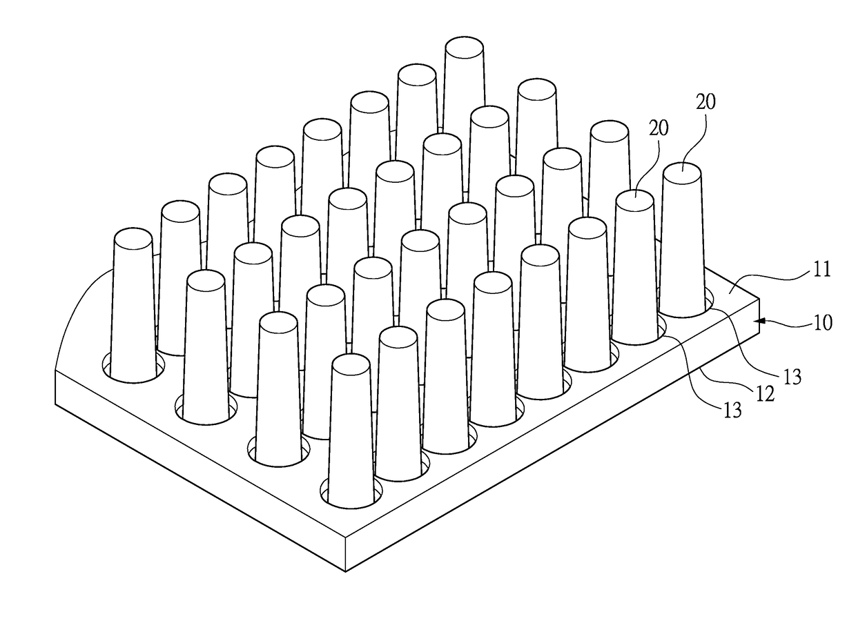
[0015]Refer to FIG. 1, which is a perspective view of a heat dissipating device of first embodiment according to the instant disclosure. The instant disclosure provides a thermal conductive substance 10, and a plurality of heat-radiating protrusions 20. The thermal conductive substance 10 has a first surface 11 and a second surface 12 opposite to the first surface 11. The heat-radiating protrusions 20 are integrally formed with the thermal conductive substance 10 and formed on the first surface 11. A plurality of turbulence-generating structures 13 are formed on the first surface 11 of the thermal conductive substance 10 in a concaved manner around the bottom ends of the heat-radiating protrusions 20 correspondingly. Thus, flowing fluid is rotating around the heat-radiating protrusions 20, so that there are vortexes formed in the concaved regions of the turbulence-generating structures 13.

[0016]This embodiment has advantages as follows. The turbulence-generating structures 13 can ob...

second embodiment

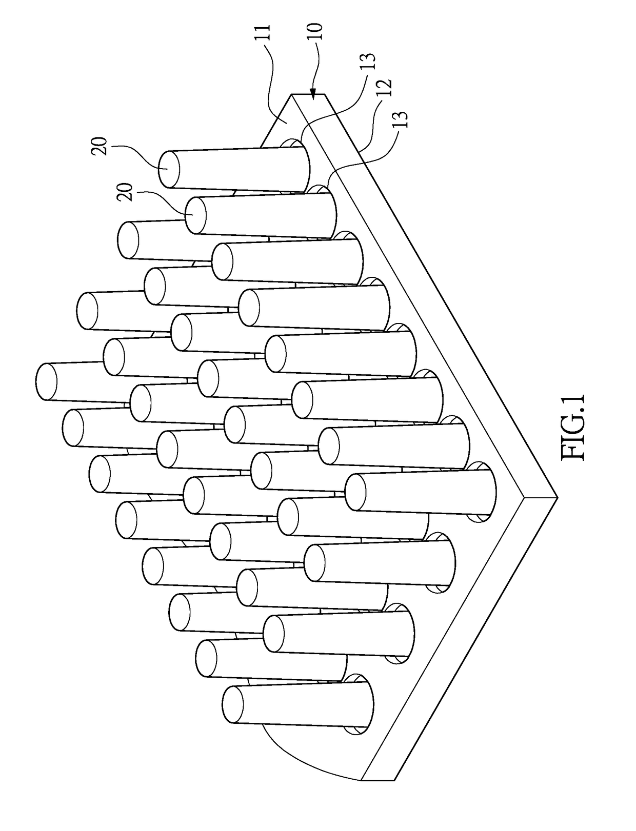
[0021]Refer to FIG. 2, which is a perspective view of a heat dissipating device of second embodiment according to the instant disclosure. Different from the above embodiment, the heat dissipating device of this embodiment has a turbulence-generating structure 13a which is concaved and formed in a strip shape, and there is a plurality of parallel rows of turbulence-generating structures 13a. Each of the turbulence-generating structures 13a surrounds the bottom ends of at least two heat-radiating protrusions 20a. In this embodiment, the strip-shaped turbulence-generating structure 13a is extended to two sides of the heat dissipating device, and surrounds seven heat-radiating protrusions 20a.

third embodiment

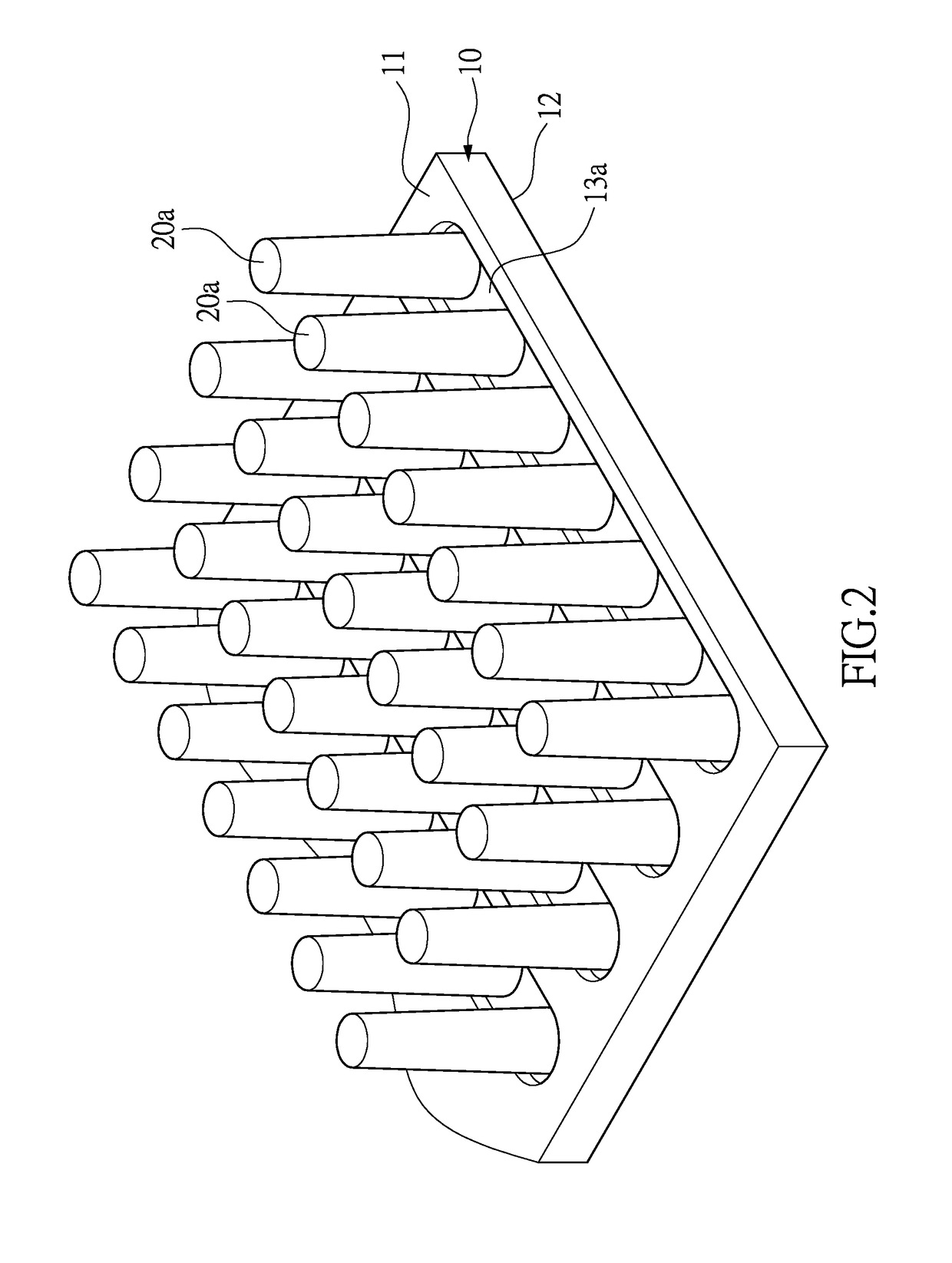
[0022]Refer to FIG. 3, which is a perspective view of a heat dissipating device of a third embodiment according to the instant disclosure. Different from the first embodiment, the heat dissipating device of this embodiment has different shaped heat-radiating protrusions. Each heat-radiating protrusion 20b is shaped in a square column, and has a turbulence-generating structure 13b. The turbulence-generating structure 13b is concaved-square-shaped surrounding the bottom end of the heat-radiating protrusion 20b.


PUM


Abstract

A heat dissipating device includes a thermal conductive substance, a plurality of heat-radiating protrusions and a plurality of turbulence-generating structures. The thermal conductive substance has a first surface and a second surface opposite to the first surface. The heat-radiating protrusions are integrally formed with the thermal conductive substance on the first surface. At least one of the turbulence-generating structures is formed on the first surface of the thermal conductive substance in concaved manner, and arranged around a bottom periphery of the heat-radiating protrusions, so as to obstruct a development of a boundary layer around the bottom of the heat-radiating protrusions.

Description

BACKGROUND OF THE INVENTION[0001]1. Field of the Disclosure[0002]The instant disclosure is related to a heat dissipating device. In particular, the instant disclosure relates to a heat dissipating device for dissipating heat, which can be applied on, for example, a water-cooled type dissipating device.[0003]2. Description of Related Art[0004]A heat dissipating device is widely used to dissipate redundant heat of an electrical element. A conventional heat dissipating device usually includes a substrate, and a plurality of fins connected to an upper surface of the substrate. The substrate is contacted with a heat source, such as an electrical element.[0005]A conventional heat dissipating device allows working fluid, such as air or liquid, to flow through the fins, so as to dissipate heat outside. However, a boundary layer with a thicker depth may happen on some portions of the conventional heat dissipating device, which will cause a problem of heat resistance. If a heat boundary layer...

Claims


Application Information

Patent Timeline
Patent Type & Authority Patents(United States)
IPC IPC(8): F28F7/00H05K7/20
CPCH05K7/20254H01L23/3677
Inventor WU, CHUN-LUNGLIN, MING-SIAN
Owner THERMAL TECH
Why Eureka
Try Eureka