
Platform vibration generator

Active Publication Date: 2018-07-10
GLOBAL MFG
View PDF25 Cites 4 Cited by
  • Summary
  • Abstract
  • Description
  • Claims
  • Application Information

AI Technical Summary

Benefits of technology

The invention is a vibrating platform that is suitable for a variety of applications that require significant vibration. The device is lightweight and stiff, with a unique design that reduces the required number of parts and the weight of the platform. The platform trusses are driven from one end of the vibrator, using a single end drive system and a flywheel assembly. This results in a stiffer and smoother-running machine, with reduced unbalanced forces and less counterbalancing forces transmitted to the flywheel. The invention provides a reliable and effective vibration system for lightweight platform vibrator applications.

Problems solved by technology

Often, complex counterbalancing is required, as well as synchronizing components.
A single side drive system is difficult to dynamically balance, but with a significantly lighter rocker arm there are less counterbalancing forces transmitted to the flywheel.

Method used


Image

  • Platform vibration generator
  • Platform vibration generator
  • Platform vibration generator

Examples


Embodiment Construction

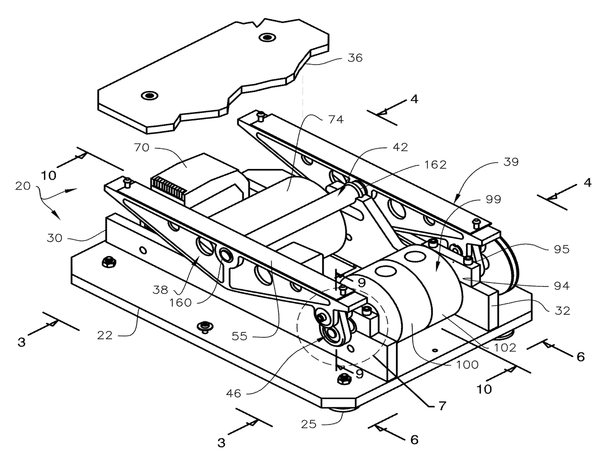
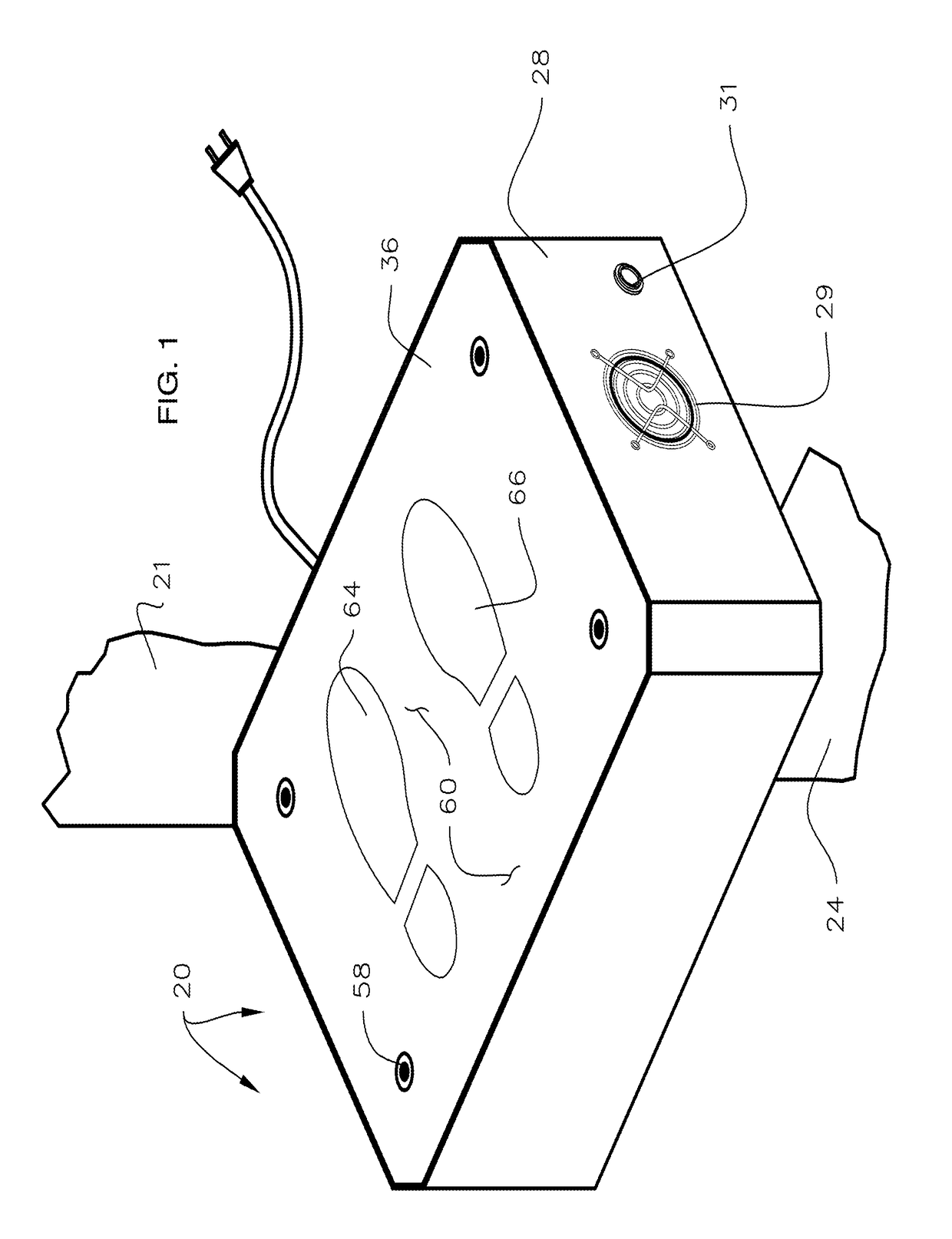
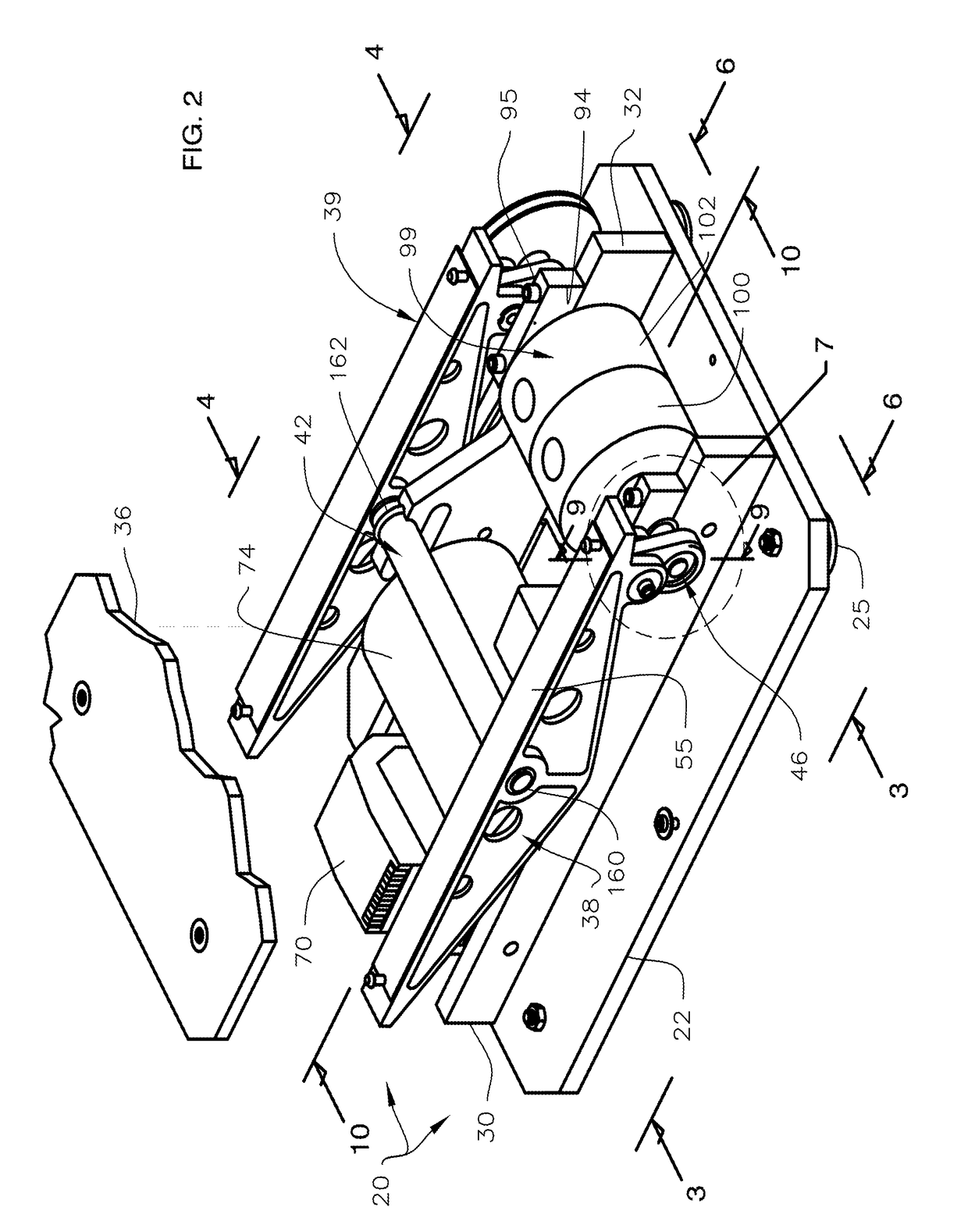
[0044]With initial reference now directed to FIGS. 1-3 of the appended drawings, a platform vibrator constructed in accordance with the best mode of the invention has been generally designated by the reference numeral 20. The preferred vibrator 20 is adapted to be employed with a variety of applications requiring firm, sustained vibration. For example, it is ideal for medical or exercise machines of the type including an upwardly rising, vertical stanchion 21 (FIG. 1) that may terminate somewhat below the eye level of a user, with handles, various controls, instruments or gauges, and computer screens or the like that are involved with a particular application. The vibrator 20 comprises a rigid, generally planar, lower base 22 (FIG. 2) in the form of a plate. Base 22 is adapted to be disposed upon a lower, supporting surface 24 (FIG. 1). Stable support may be provided by a plurality of adjustable feet 25 that may have through-bolts 26 fastened to base plate 22 by conventional fastene...


PUM


Abstract

A vibrator comprises an upper, lightweight, honeycomb rocker plate suspended above a rigid, lower base by a pair of triangular truss rocker arms. A pair of rigid, parallel, spaced-apart stringers within the vibrator rise upwardly from the lower base. A rocker shaft extending between the stringers pivots the rocker arms near their midpoint. A motor secured to the base within the vibrator drives a spaced-apart flywheel assembly that is mounted with a crankshaft journaled between the stringers. The motor is coupled to the flywheel assembly with a drive belt extending between suitable pulleys. The flywheel assembly crankshaft terminates in spaced apart, offset portions that reciprocate connecting rods linked to one end of the triangular truss rocker arms that vigorously vibrate the rocker plate.

Description

CROSS REFERENCE TO RELATED APPLICATION[0001]This application is based upon, and claims priority from, previously filed U.S. Provisional Application Ser. No. 61 / 982,983, entitled “Platform Vibration Generator”, filed 23 Apr. 2014, inventor Rodney D. Treat.BACKGROUND OF THE INVENTIONI. Field of the Invention[0002]The present invention relates generally to motor-driven vibrator apparatus. More particularly, the present invention relates to electrically powered, vibrating platforms of the type used with various exercise machines, medical treatment apparatus, and vibration test stands and equipment.II. Description of the Prior Art[0003]A variety of vibration-producing machines utilized for diverse purposes exist in the art. Many modern appliances and critical devices and machines used in aeronautics and aviation, electrical power generation, and with automotive applications, are routinely subject to vibration and shock testing. Existing vibration testing standards are widely accepted and...

Claims


Application Information

Patent Timeline
IPC IPC(8): A61H1/00A61H23/02
CPCA61H1/005A61H23/02A61H1/003A61H2201/0138A61H1/001
Inventor TREAT, RODNEY DKLIGMAN, STANISLAV PJANOSKY, THOMAS A
Owner GLOBAL MFG
Learn More