Track roller assembly and method

a technology of roller shaft and through-bore, which is applied in the direction of endless track vehicles, vehicles, transportation and packaging, etc., can solve the problems of wear of the surface of the roller shaft and the through-bore, and achieve the effect of reducing the shaft length

Active Publication Date: 2018-07-17
CATERPILLAR INC
View PDF14 Cites 4 Cited by
  • Summary
  • Abstract
  • Description
  • Claims
  • Application Information

AI Technical Summary

Benefits of technology

[0005]In one aspect of the present disclosure, a method for assembling a track roller is disclosed. The method may include inserting a roller shaft having a shaft outer surface with a shaft outer diameter into a roller inner surface of the track roller having a varying roller inner diameter, wherein the shaft outer surface and the roller inner surface are configured so that the track roller can rotate about the roller shaft, and press fitting a first collar onto a first shaft end of the roller shaft and a second collar onto a second shaft end of the roller shaft, and forcing the first collar and the second collar axially inwardly until axially inward movement of the first collar is prevented by a first engagement shoulder of the track roller and axially inward movement of the second collar is prevented by a second engagement shoulder of the track roller. The method may further include applying a compressive axial load to the roller shaft to reduce a shaft length of the roller shaft from a normal shaft length to a compressed shaft length, wherein the roller shaft moves relatively inwardly relative to the first collar and the second collar, and removing the compressive axial load from the roller shaft so that the roller shaft extends back to the normal shaft length and the first collar and the second collar move axially farther apart as the roller shaft extends back to the normal shaft length.
[0007]In a further aspect of the present disclosure, a method for assembling a track roller is disclosed. The method may include press fitting a first flange bushing and a second flange bushing into a roller inner surface of the track roller having a varying roller inner diameter, wherein the first flange bushing has a first bushing body having a hollow cylindrical shape and a first bushing flange extending radially outwardly from a first bushing end, and the second flange bushing has a second bushing body having a hollow cylindrical shape and a second bushing flange extending radially outwardly from a second bushing end, wherein the first flange bushing and the second flange bushing are press fit axially inwardly until the first bushing flange engages a first engagement shoulder and the second bushing flange engages a second engagement shoulder. The method may further include inserting a roller shaft having a shaft outer surface with a shaft outer diameter into the roller inner surface of the track roller, wherein the shaft outer surface, the first bushing body and the second bushing body are configured to provide a shaft radial clearance so that the track roller can rotate about the roller shaft, press fitting a first collar onto a first shaft end of the roller shaft until a first collar inward end engages the first bushing flange and a second collar onto a second shaft end of the roller shaft until a second collar inward end engages the second bushing flange, applying a compressive axial load to the roller shaft to reduce a shaft length of the roller shaft from a normal shaft length to a compressed shaft length, wherein the roller shaft moves relatively inwardly relative to the first collar and the second collar, and removing the compressive axial load from the roller shaft so that the roller shaft extends back to the normal shaft length and the first collar and the second collar move axially farther apart as the roller shaft extends back to the normal shaft length.

Problems solved by technology

The track-type machine may operate in adverse environments wherein the track roller assemblies may be exposed to abrasive mixtures of water, dirt, sand, rock or other materials, and even chemical elements.
These contaminants may enter a space between the roller shaft and the through-bore of the track roller and lead to wear of the surfaces of the roller shaft and the through-bore.

Method used


Image

  • Track roller assembly and method
  • Track roller assembly and method
  • Track roller assembly and method

Examples


Embodiment Construction

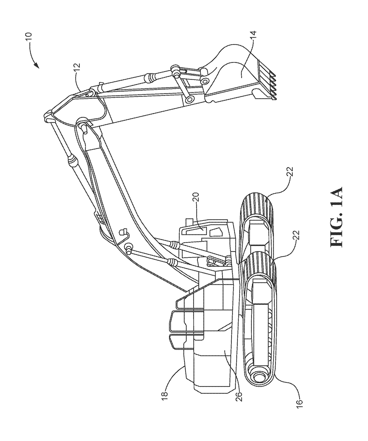
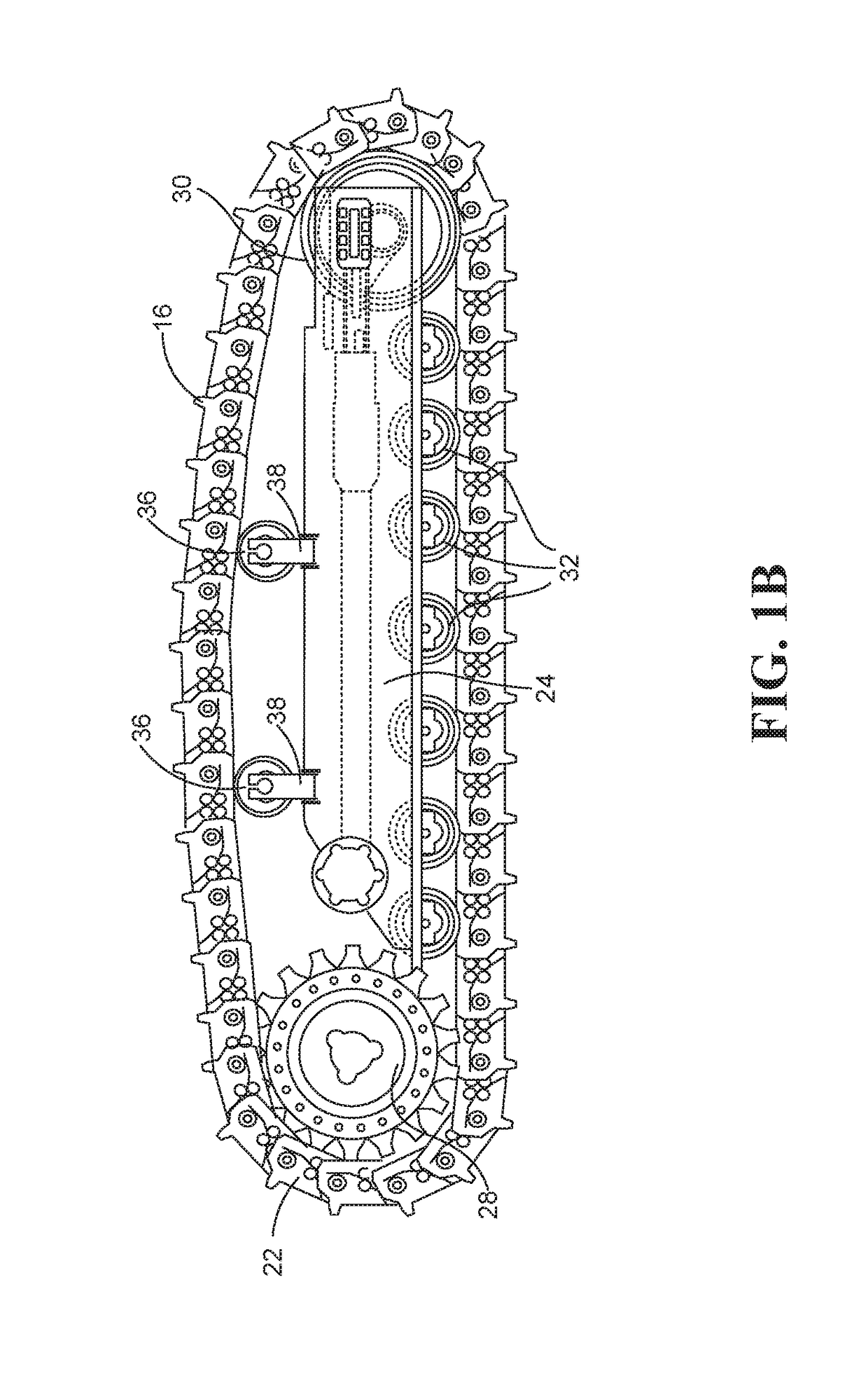
[0022]Referring to FIGS. 1A and 1B, a track-type machine 10 may embody a mobile machine that performs some type of operation associated with an industry such as mining, construction, farming, transportation, waste handling or any other industry known in the art. For example, the machine 10 may be an earth moving machine such as a hydraulic excavator or other suitable machine. The machine 10 may include an implement system 12 configured to adjust the position or orientation of an implement such as a bucket 14, a drive system in the form of a track undercarriage 16 for propelling the machine 10, a power source 18 that provides power to the implement system 12 and the undercarriage 16, and an operator station 20 for operator control of the implement system 12 and the undercarriage 16. Though a hydraulic excavator is illustrated, the rollers disclosed herein may be implemented in any other types of machines having an undercarriage, such as material loaders, tractors and the like.

[0023]P...


PUM


Abstract

A track roller assembly may have a track roller, a roller shaft and collars press fit onto either end of the roller shaft to retain the track roller on the roller shaft with an axial clearance between the collars and the track roller. During assembly, the collars may be press fit onto the shaft ends and forced axially inwardly until further axial movement of the collars is prevented by engagement shoulders of the track roller. A compressive axial load may be applied to the roller shaft to reduce a shaft length of the roller shaft and to cause the roller shaft to slide inwardly relative to the collars. The compressive axial load is removed from the roller shaft so that the roller shaft extends back to the normal shaft length and the collars move axially farther apart as the roller shaft extends back to the normal shaft length.

Description

TECHNICAL FIELD[0001]The present disclosure relates generally to track-type machines and, more particularly, to track roller assemblies for track-type machines and methods for fabricating track roller assemblies.BACKGROUND[0002]Track-type machines, such as excavators, bulldozers, track-loaders and skid-steer loaders, are used in a variety of applications. Generally speaking, these machines have an operator station, a power source, an undercarriage and a pair of track systems laterally flanking the machine. Each track system may include a roller frame positioned along a lengthwise-extending direction of the track-type machine, a drive sprocket mounted on the roller frame and rotatably driven by the power source, and one or more idler wheels also mounted for rotation on the roller frame. An endless track that circumscribes the drive sprocket and the one or more idler wheels. The endless track is engaged by the drive sprocket so the power source can drive the endless track over the dri...

Claims


Application Information

Patent Timeline
Patent Type & Authority Patents(United States)
IPC IPC(8): B62D55/32B62D55/15B62D55/14B62D55/092B62D55/088B62D55/08B62D55/06E02F3/32
CPCB62D55/32B62D55/088B62D55/092B62D55/15B62D55/14E02F3/32B62D55/06B62D55/08B60Y2200/25
Inventor RECKER, ROGER L.
Owner CATERPILLAR INC
Why Eureka
Try Eureka