Rotary table

a rotary table and rotor technology, applied in the field of rotor tables, can solve the problems of reduced responsiveness of the clamping mechanism, difficult function application, use of coil springs, etc., and achieve the effect of sufficient responsiveness and clamping torqu

Active Publication Date: 2018-07-24
FANUC LTD
View PDF30 Cites 3 Cited by
  • Summary
  • Abstract
  • Description
  • Claims
  • Application Information

AI Technical Summary

Benefits of technology

[0013]According to the configuration of the present invention described above, a biasing function and a rotation stopping function can be achieved through a simple structure to provide a rotary table that includes a piston type clamping mechanism demonstrating enough responsiveness and clamping torque.

Problems solved by technology

However, such a method requires more operating fluid to fill a space for accommodating the coil spring, which could lead to reduced responsiveness in a clamping mechanism.
Moreover, such a method using a coil spring is also disadvantageous because the method makes difficult to apply a function for preventing a piston from being rotated, in addition to insufficient clamping torque.
However, since the structure disclosed in JP 5057568 B2 basically uses a spring member for either clamping or unclamping, it is difficult to pneumatically drive the structure for both clamping and unclamping operations, unlike a typical piston structure.
However, in the structure disclosed in JP 5468581 B2, because a piston does not face a pressure chamber as can be seen in a piston structure, a pneumatic path might be complicated, thus the operating speed could be affected.

Method used


Image

  • Rotary table
  • Rotary table
  • Rotary table

Examples


Embodiment Construction

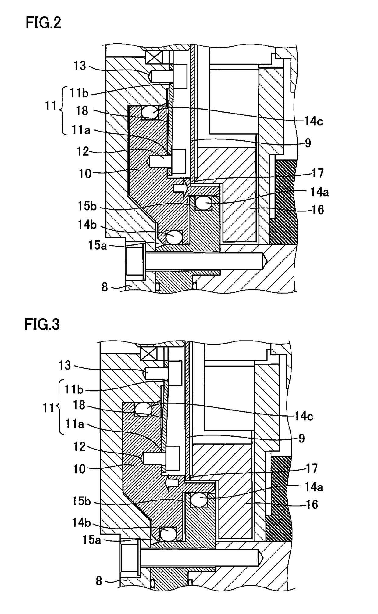
[0022]A description will hereinafter be given of two embodiments of the present invention with consultation of drawings.

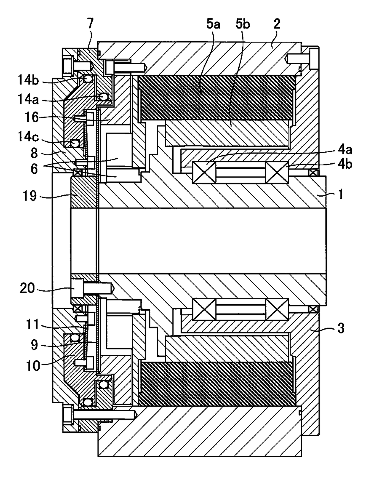
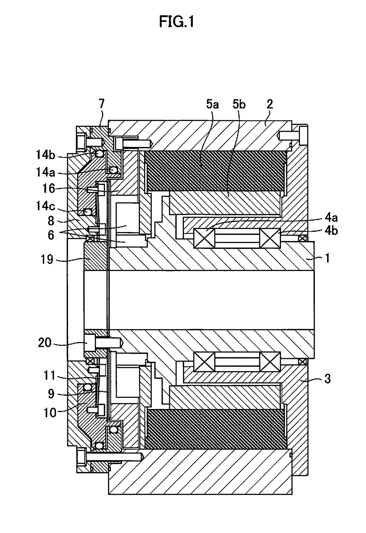
[0023]FIG. 1 is a cross-sectional view entirely illustrating a normally-clamping type indexing rotary table having a direct drive mechanism. Such a rotary table may be mounted for use, for example, on a machining table for a machine tool.

[0024]A shaft 1 is rotatably supported via main bearings 4a and 4b by a housing 3 fixed to a case 2. A stator 5a of a motor for rotating the shaft 1 is fixed to the housing 3. A rotor 5b of the motor is attached to the shaft 1. The shaft 1 attached with the rotor 5b is rotatably supported relative to the case 2. An encoder 6 (a detection side is fixed to the case 2, while an encoder plate is fixed to the shaft 1) for detecting a rotation position and a speed of the shaft 1, a cylinder 7, and a rear plate 8 are also fixed to the case 2.

[0025]A brake disc 9 is tightly held between an end face of the shaft 1 and an end face of a mount...


PUM


Abstract

A rotary table includes a clamping mechanism including a piston driven by operating fluid in a direction of either of clamping and unclamping a brake disc, and a biasing means fixed by a case and the piston to always bias the piston in a direction of either of clamping and unclamping the brake disc by a recovery force of elastic deformation.

Description

RELATED APPLICATIONS[0001]The present application claims priority to Japanese Patent Application Number 2015-033874 filed Feb. 24, 2015 and Japanese Patent Application Number 2016-016012 filed Jan. 29, 2016, the disclosure of which is hereby incorporated by reference herein in its entirety.BACKGROUND OF THE INVENTION[0002]1. Field of the Invention[0003]The present invention relates to a rotary table.[0004]2. Description of the Related Art[0005]A rotary table is, for example, mounted in a machine tool that is controlled by a numerical controller, and is used to secure a workpiece, a jig, and the like on a rotating portion of the rotary table for indexing, rotation supporting, and other purposes.[0006]Such a rotary table is arranged with a clamping mechanism that takes a more important role than other components of the rotary table because how quickly this clamping mechanism operates affects a cycle time for processing a workpiece with a machine tool, i.e. such a clamping mechanism is...

Claims


Application Information

Patent Timeline
Patent Type & Authority Patents(United States)
IPC IPC(8): B23Q16/10
CPCB23Q16/105B23Q2220/004
Inventor NISHIMURA, TAKUMA
Owner FANUC LTD
Why Eureka
Try Eureka