
Coupling element for an electric switching device

a technology of electric switching device and coupling element, which is applied in the direction of air-break switch, mechanical apparatus, gearing, etc., to achieve the effect of preventing any loss of tension

Active Publication Date: 2018-07-24
SIEMENS AG
View PDF12 Cites 2 Cited by
  • Summary
  • Abstract
  • Description
  • Claims
  • Application Information

AI Technical Summary

Benefits of technology

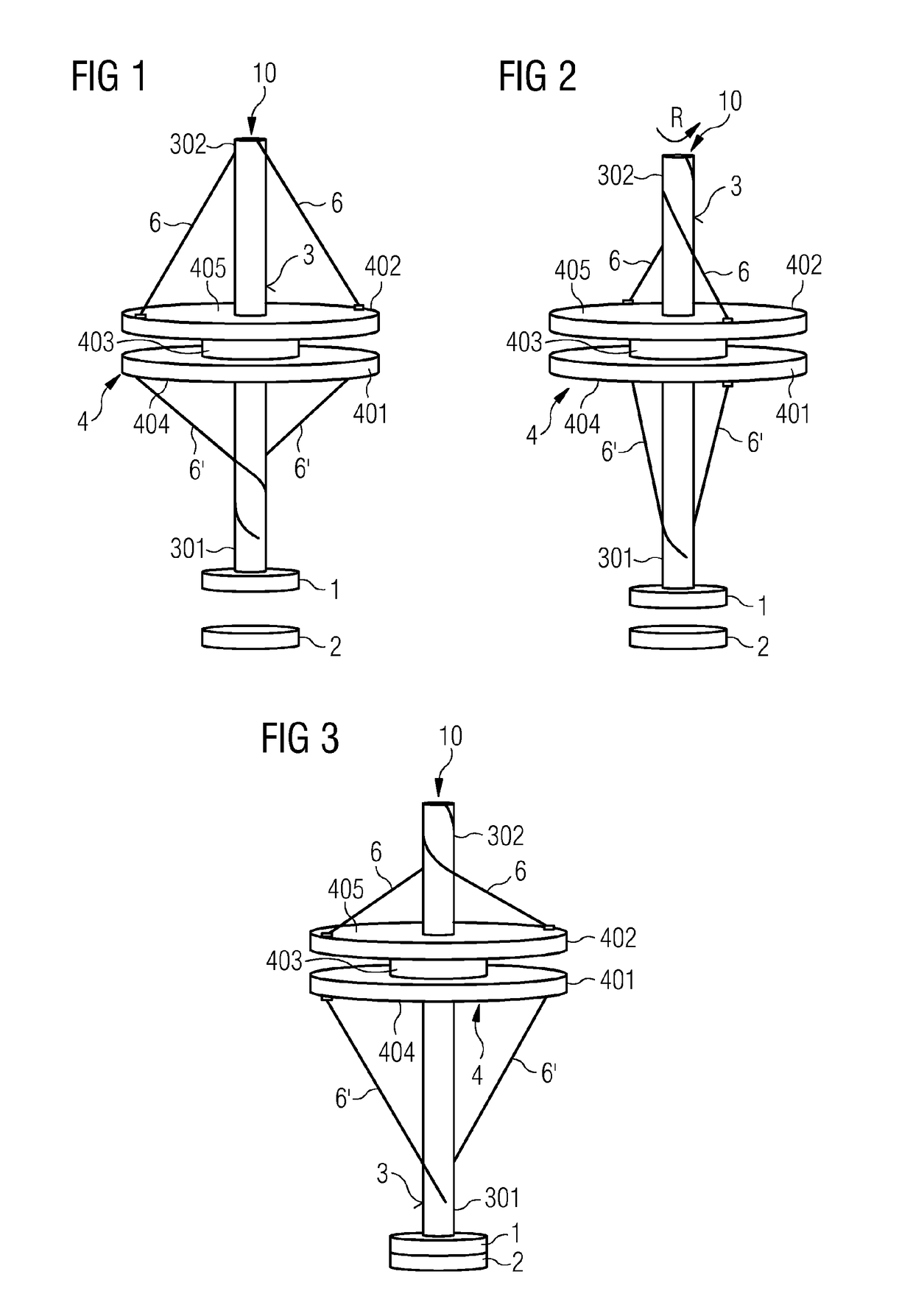
[0016]In an embodiment, on one or both sides of the rotation body, the wires arranged on a respective side are configured in one or more pairs of wires, where the wires of a respective pair, in an overhead view of the respective side of the rotation body, are offset by an angle of 180° around the longitudinal axis of the winding body. A simple design of the coupling element is thus achieved.
[0017]In a further embodiment, on both sides of the rotation body, the wires are arranged such that, upon a rotary movement of the rotation body in the one direction, the wires are wound onto the one side and unwound from the other side and, upon a rotary movement of the rotation body in the other direction, the wires are unwound from the one side and wound onto the other side. The kinematics for both the opening and the closing of the switching contacts may be achieved in a simple manner.
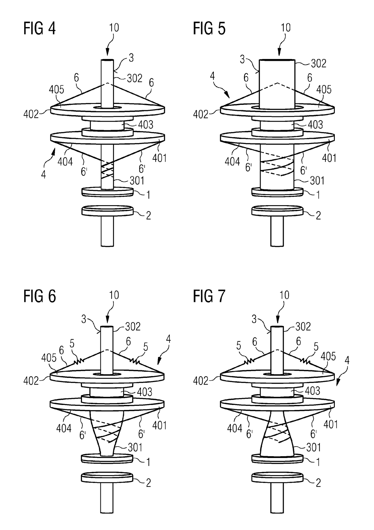
[0020]In an embodiment thus described, the thickness of the winding body, on the side of the rotation body that faces the end of the winding body upon which the first switching contact is arranged, increases in the longitudinal direction of the winding body through to the end. A progressive translational characteristic is achieved. The first switching contact, in the event of a small clearance between the first switching contact and the second switching contact, moves more rapidly, such that the electrical contact is opened and closed more rapidly. Electrical flashovers between the first switching contact and the second switching contact may be prevented. The thickness of the winding body, on the other side of the rotation body, decreases in the longitudinal direction of the winding body through to the other end of the winding body. The shape of the winding body on the one side corresponds to the shape of the winding body on the other side. A uniform winding and unwinding of the wires on both sides of the rotation body is achieved, and any loss of tension in the wires is prevented.
[0021]In an embodiment, the thickness of the winding body, on the side of the rotation body that faces the end of the winding body upon which the first switching contact is arranged, decreases in the longitudinal direction of the winding body through to the end. A degressive translational characteristic is achieved where the first switching contact, in the event of a small clearance between the first switching contact and the second switching contact, moves more slowly. In an embodiment the thickness of the winding body, on the other side of the rotation body, increases in the longitudinal direction of the winding body through to the other end of the winding body. The shape of the winding body on the one side corresponds to the shape of the winding body on the other side. A uniform winding and unwinding of the wires on both sides is achieved, and any loss of tension in the wires is thus counteracted.

Problems solved by technology

However, a simple and compact design is countered by the complex kinematics involved in the movement of switching contacts in electric switching devices.

Method used


Image

  • Coupling element for an electric switching device
  • Coupling element for an electric switching device
  • Coupling element for an electric switching device

Examples


Embodiment Construction

[0032]Embodiments provide a coupling element. The function of the coupling element includes the opening and closing of the switching contacts in a vacuum switching tube. However, the coupling element may also be employed in other switching devices for the opening and closing of an electrical contact.

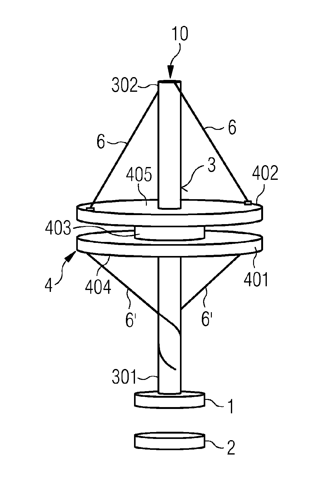
[0033]FIGS. 1 to 3 depicts an embodiment of a coupling element 10. A contact system including the disk-shaped switching contacts 1 and 2 is actuated. The switching contact 1 moves in relation to the switching contact 2. By the contacting of the two switching contacts 1 and 2, an electric circuit is closed, and a current flux is delivered via the electrically-conductive winding body 3 and the contact system of the switching contacts 1 and 2. The current flux may be interrupted once more by the opening of the contact system, by the separation of the two switching contacts 1 and 2.

[0034]The switching contact 1 is attached to a lower end 301 of the winding body 3, also referred to as the win...


PUM


Abstract

A coupling element is provided for an electric switching device wherein the coupling element includes a first switching contact for opening and closing an electric contact by a second switch contact. The coupling element has an oblong winding body having two ends that are opposite in the longitudinal direction of the longitudinal axis thereof, wherein the first switch contact is arranged on one end. The coupling element furthermore includes a rotation body through which the winding body extends and that is provided for coupling to a drive to carry out a rotation movement by the drive, wherein the rotation body includes two sides of which one faces one end (of the winding body and the other faces the other end of the winding body.

Description

CROSS REFERENCE TO RELATED APPLICATIONS[0001]The present patent document is a § 371 nationalization of PCT Application Serial Number PCT / EP2015 / 081332, filed Dec. 29, 2015, designating the United States, which is hereby incorporated by reference. This patent document also claims the benefit of DE 102015200135.0, filed on Jan. 8, 2015, which is also hereby incorporated by reference.FIELD[0002]Embodiments relate to a coupling element for an electric switching device.BACKGROUND[0003]Electric switching devices are used in the low-voltage, medium-voltage, and high-voltage range for the opening and closing of electrical switching contacts. Vacuum switching tubes, in which the electrical switching contacts are arranged in a vacuum, are used, thereby permitting a high dielectric withstand. Electric switching devices may be of simple and compact design. However, a simple and compact design is countered by the complex kinematics involved in the movement of switching contacts in electric switc...

Claims


Application Information

Patent Timeline
Patent Type & Authority Patents(United States)
IPC IPC(8): H01H33/666H01H33/664H01H3/36
CPCH01H33/666H01H33/664H01H3/36H01H2205/002F16H19/0654
Inventor BACHMAIER, GEORGGODECKE, ANDREASVONTZ, THOMASZOLS, WOLFGANG
Owner SIEMENS AG
Learn More