Supercharge Your Innovation With Domain-Expert AI Agents!

Reference voltage generation circuit

a reference voltage and circuit technology, applied in the field of reference voltage generation circuits, can solve the problem that the reference voltage should be relatively high

Active Publication Date: 2018-07-31
COMMISSARIAT A LENERGIE ATOMIQUE ET AUX ENERGIES ALTERNATIVES
View PDF8 Cites 3 Cited by
  • Summary
  • Abstract
  • Description
  • Claims
  • Application Information

AI Technical Summary

Benefits of technology

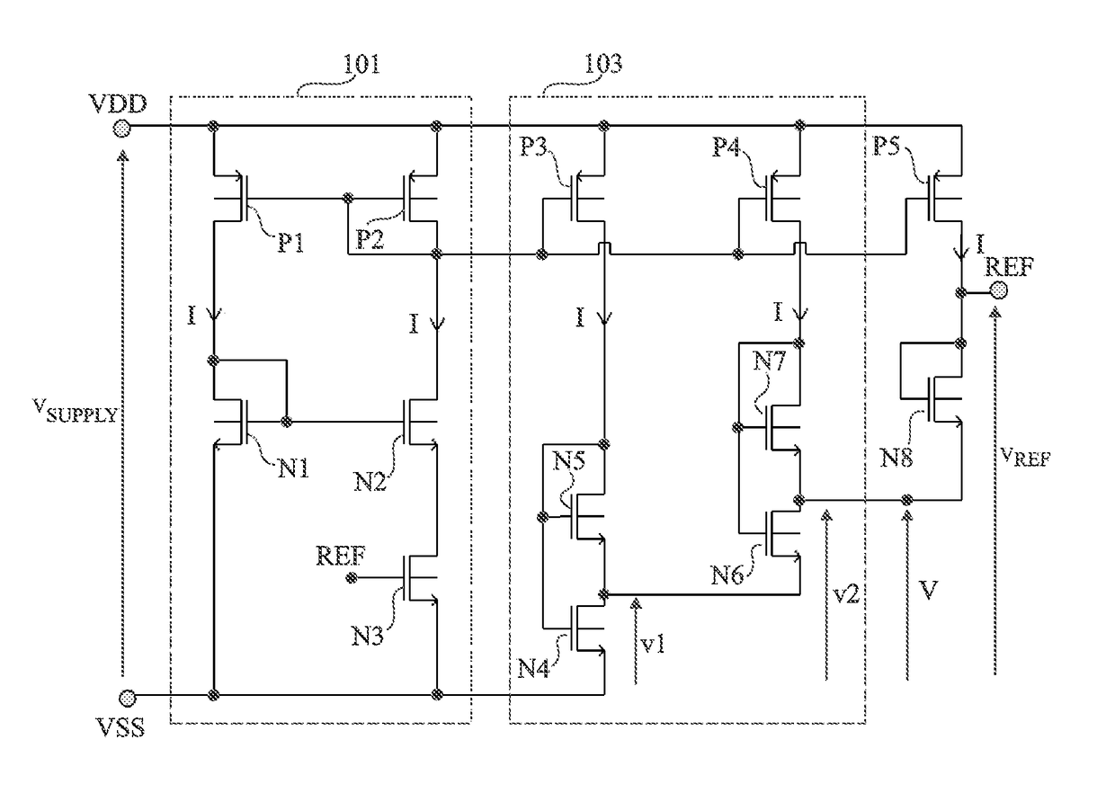
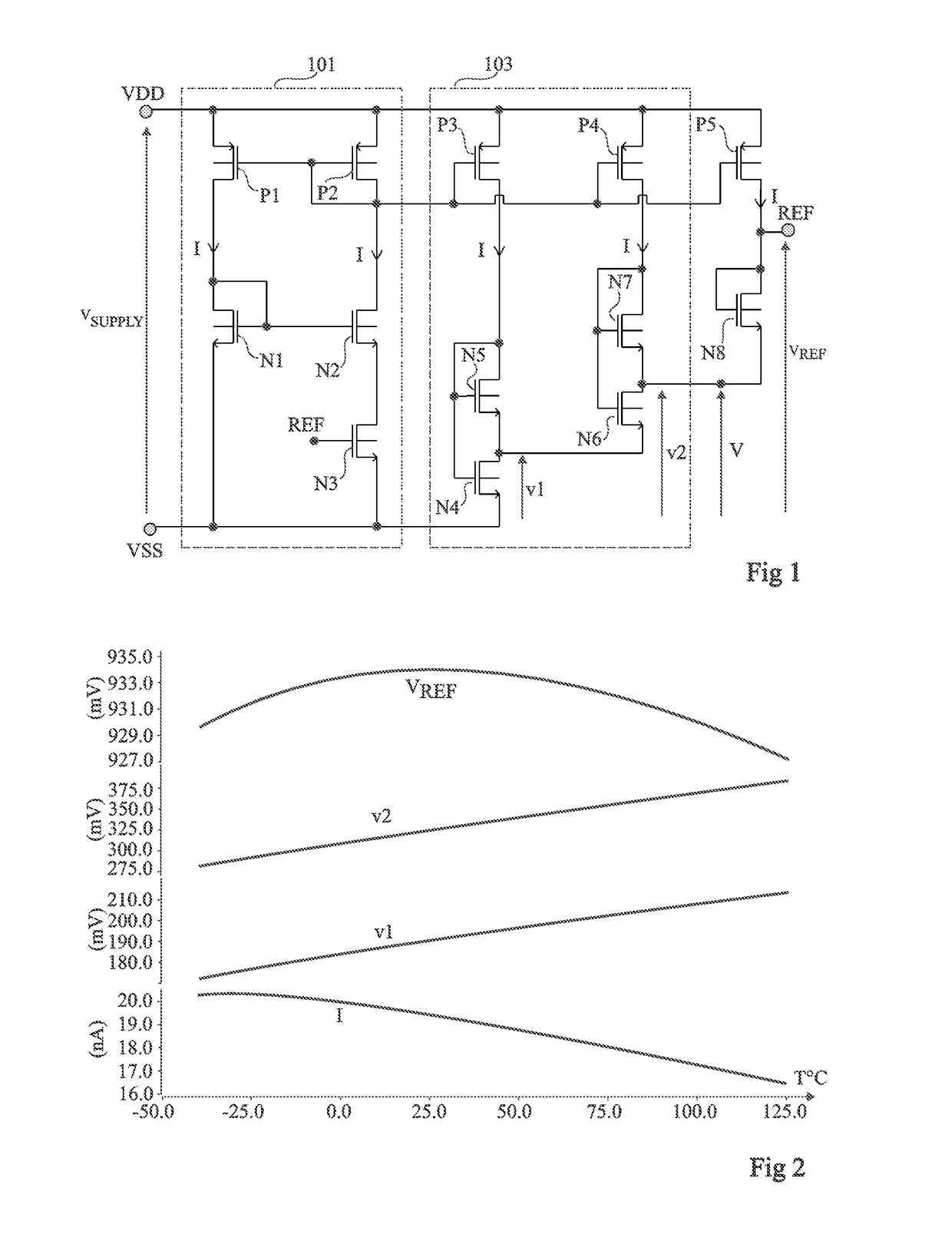
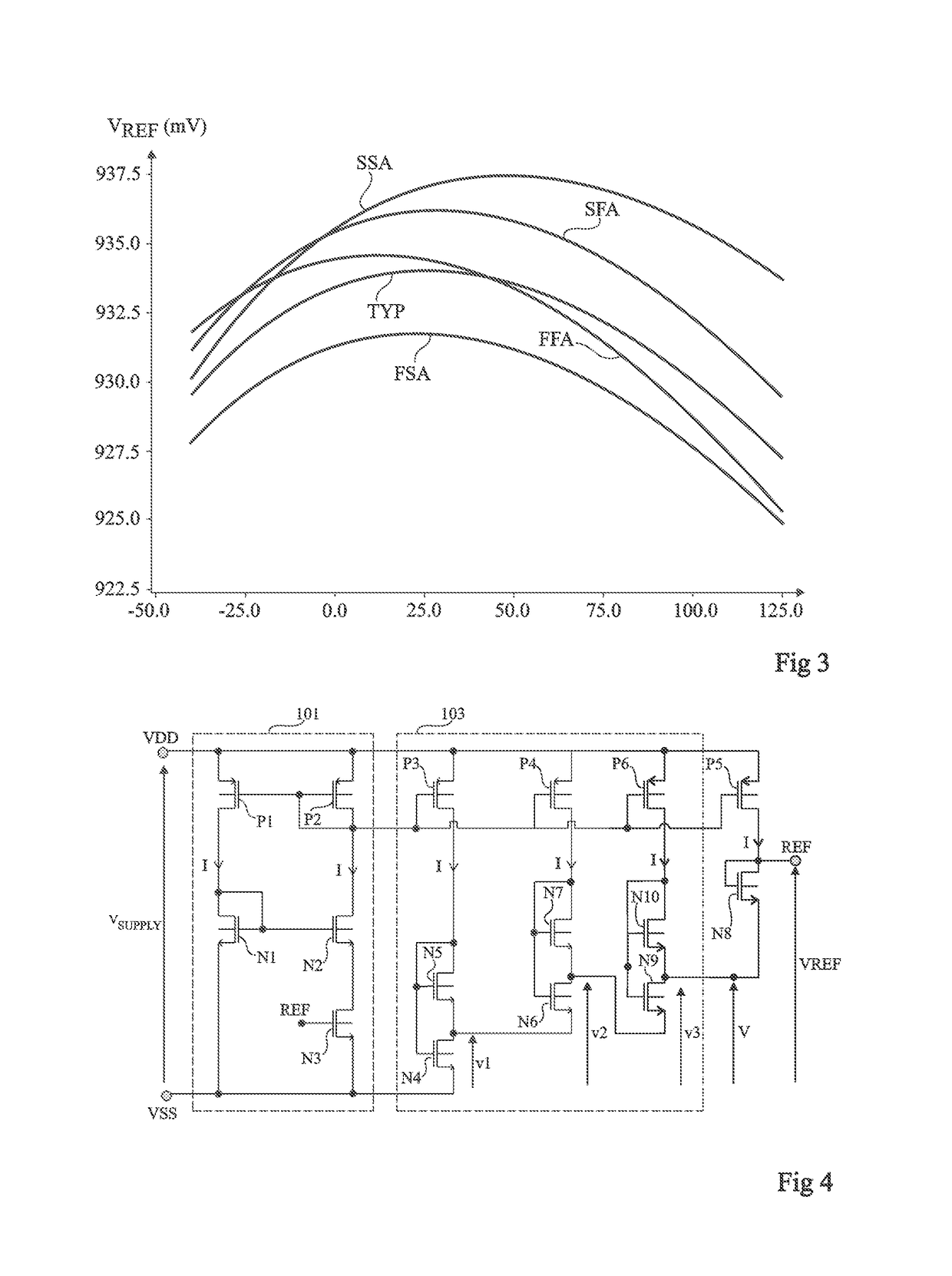
The patent describes a circuit that generates a reference voltage in FDSOI technology. The circuit includes a first circuit for generating a CTAT-type bias current, a second circuit for generating a PTAT-type voltage, and a current mirror. The front surface gates of the first and second transistors are connected to the conduction node of the second transistor opposite to the first transistor, and a third transistor has a conduction node connected to a node for supplying the output voltage of the second circuit. The current mirror imposes currents proportional to the bias current in both the first and second branches. The transistors are of LVT or RVT type, and the circuit includes additional transistors for better performance and reliability. The technical effects of this invention include improved accuracy and stability of reference voltage, as well as better performance and reliability of the circuit components.

Problems solved by technology

A disadvantage of such circuits is that, to obtain a good temperature stability, the reference voltage should be relatively high, typically in the order of 1.2 V.

Method used


Image

  • Reference voltage generation circuit
  • Reference voltage generation circuit
  • Reference voltage generation circuit

Examples


Embodiment Construction

[0027]The same elements have been designated with the same reference numerals in the different drawings. For clarity, only those elements which are useful to the understanding of the described embodiments have been shown and detailed. In particular, the uses which may be made of the described reference voltage generation circuits are not detailed, the described embodiments being compatible with usual applications of a reference voltage generation circuit. Unless otherwise specified, expressions “approximately”, “about”, “substantially”, and “in the order of” mean to within 10%, preferably to within 5%. In the present description, term “connected” is used to designate a direct electric connection, with no intermediate electronic component, for example, by means of one or a plurality of conductive tracks, and term “coupled” or term “linked” is used to designate either a direct electric connection (then meaning “connected”) or a connection via one or a plurality of intermediate compone...


PUM


Abstract

An FDSOI reference voltage generation circuit, including a CTAT current generation circuit; a PTAT-type voltage generation circuit including a first branch including first and second series-connected transistors, the front surface gates of the first and second transistors being connected to the conduction node of the second transistor opposite to the first transistor; a third diode-assembled transistor having a conduction node connected to an output node of the PTAT voltage generation circuit and having its other conduction node forming a reference voltage supply node; and a current mirror; wherein the first and second transistors are of LVT type and the third transistor is of RVT type.

Description

CROSS-REFERENCE TO RELATED APPLICATION[0001]This application claims the priority benefit of French patent application number 15 / 61551, filed Nov. 30, 2015, which is hereby incorporated by reference in its entirety to the maximum extent allowable by law.BACKGROUND[0002]The present disclosure generally relates to the field of electronic systems, and more particularly aims at a reference voltage generation circuit.DISCUSSION OF THE RELATED ART[0003]Many electronic systems use a reference voltage generation circuit to generate, from a DC power supply voltage of the system, a DC reference voltage independent from fluctuations of the power supply voltage and independent from temperature variations. Such a circuit is generally integrated in a semiconductor chip, which may be an autonomous chip or which may comprise other circuits intended to implement other functions of the system.[0004]Reference voltage generation circuits formed from bipolar transistors have already been provided. A disa...

Claims


Application Information

Patent Timeline
Patent Type & Authority Patents(United States)
IPC IPC(8): G05F3/26
CPCG05F3/267G05F3/242
Inventor QUELEN, ANTHONY
Owner COMMISSARIAT A LENERGIE ATOMIQUE ET AUX ENERGIES ALTERNATIVES
Features
  • R&D
  • Intellectual Property
  • Life Sciences
  • Materials
  • Tech Scout
  • Unparalleled Data Quality
  • Higher Quality Content
  • 60% Fewer Hallucinations
Learn More