Ladar transmitter with optical field splitter/inverter

a technology of optical field splitter and laser transmitter, which is applied in the direction of electromagnetic wave reradiation, measurement devices, instruments, etc., can solve the problems of large data bandwidth use, large size, large weight, and large power requirements of conventional ladar solutions for computer vision problems, and limit their effective use to costly applications

Active Publication Date: 2018-08-07
AEYE INC
View PDF72 Cites 100 Cited by
  • Summary
  • Abstract
  • Description
  • Claims
  • Application Information

AI Technical Summary

Benefits of technology

[0008]This is because, while even the world's largest radars have thousands of beam choices upon which to dwell, even a small automotive ladar system fitting in the palm of the hand routinely has 100,000+ or even millions of choices for dwell. This leads to two general design choices for ladar engineers: (i) mechanically step from dwell to dwell, or (ii) use resonant mirrors that rapidly scan through the scene. Design approach (i) is precise and adaptable but is extremely slow in environments where there are large numbers of interrogation cells present. Design approach (ii) has historically been non-adaptable. To improve upon these conventional design approaches, the inventors disclose techniques by which one can reduce the disadvantages of resonant mirror-based ladar while achieving much of the acuity and specificity that historically has only been available to mechanical stepping techniques and without losing the speed advantages of resonant scanning mirrors.
[0009]In example embodiments, the inventors disclose designs for a field splitter / inverter that can be used in combination with high speed scans such as Lissajous scans to improve the gaze of a ladar transmitter on desired scan areas (such as a center region of a scan area). The inventors further disclose how an induced periodic phase drift can be incorporated into a Lissajous scan to further improve gaze by reducing scan gaps in desired regions, while doing so in a manner that can ensure low amplitude and zero impact on periodicity, thereby ensuring beam quality and preserving mensuration.
[0010]In example embodiments, the inventors also disclose a compact beam scanner assembly that includes an ellipsoidal conjugate reflector reimaging mirror. The ellipsoidal mirror can be positioned optically between first and second scanable mirrors. A lens can be positioned optically upstream from the first scanable mirror. Such an arrangement can provide (among other benefits) a compact beam scanner design where the two scanable mirrors are equally sized and placed closely together within the assembly. Moreover, reimaging can be especially useful when used in combination with field inversion, since it limits the additional upscope headroom needed for an inverter lens.

Problems solved by technology

However, conventional ladar solutions for computer vision problems suffer from high cost, large size, large weight, and large power requirements as well as large data bandwidth use.
These complicating factors have largely limited their effective use to costly applications that require only short ranges of vision, narrow fields-of-view and / or slow revisit rates.
However, these conventional systems are believed to suffer from a number of shortcomings.
For example, flash ladar systems require a very high energy per pulse laser, which is not only costly but can also be an eye hazard.
Furthermore, the read-out integrated circuits for flash ladar systems are typically quite noisy.
Also, the wide field-of-view signal-to-noise ratio (SNR) for flash ladar systems is typically very low, which results in short ranges, thereby detracting from their usefulness.
While radars have been highly optimized with scheduling methods to dwell (gaze) where gaze is needed when gaze is needed, conventional ladar systems today do not share this dwell optimality.
Design approach (i) is precise and adaptable but is extremely slow in environments where there are large numbers of interrogation cells present.
Design approach (ii) has historically been non-adaptable.

Method used


Image

  • Ladar transmitter with optical field splitter/inverter
  • Ladar transmitter with optical field splitter/inverter
  • Ladar transmitter with optical field splitter/inverter

Examples


Embodiment Construction

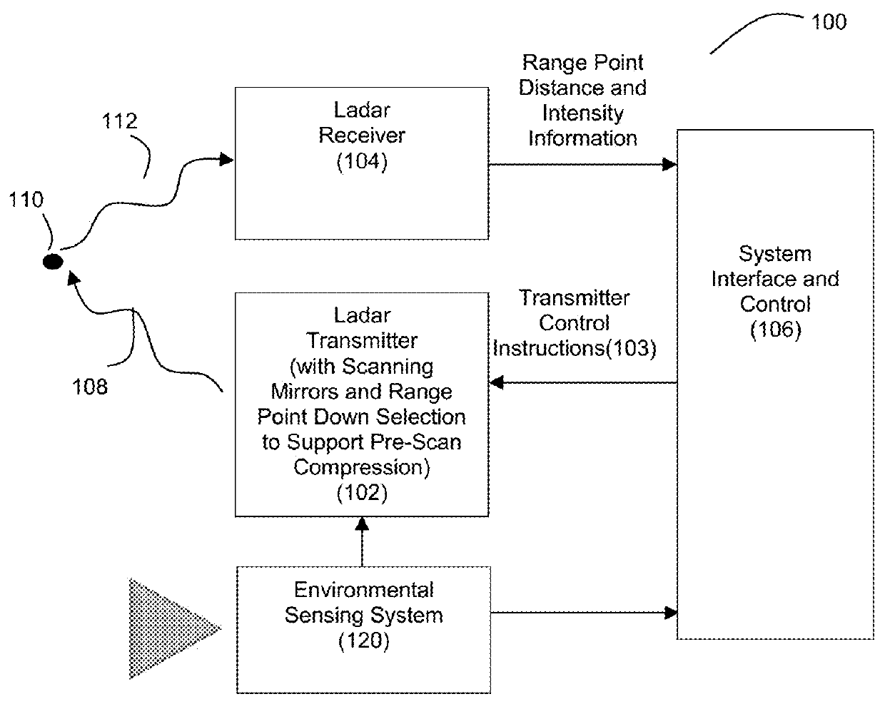
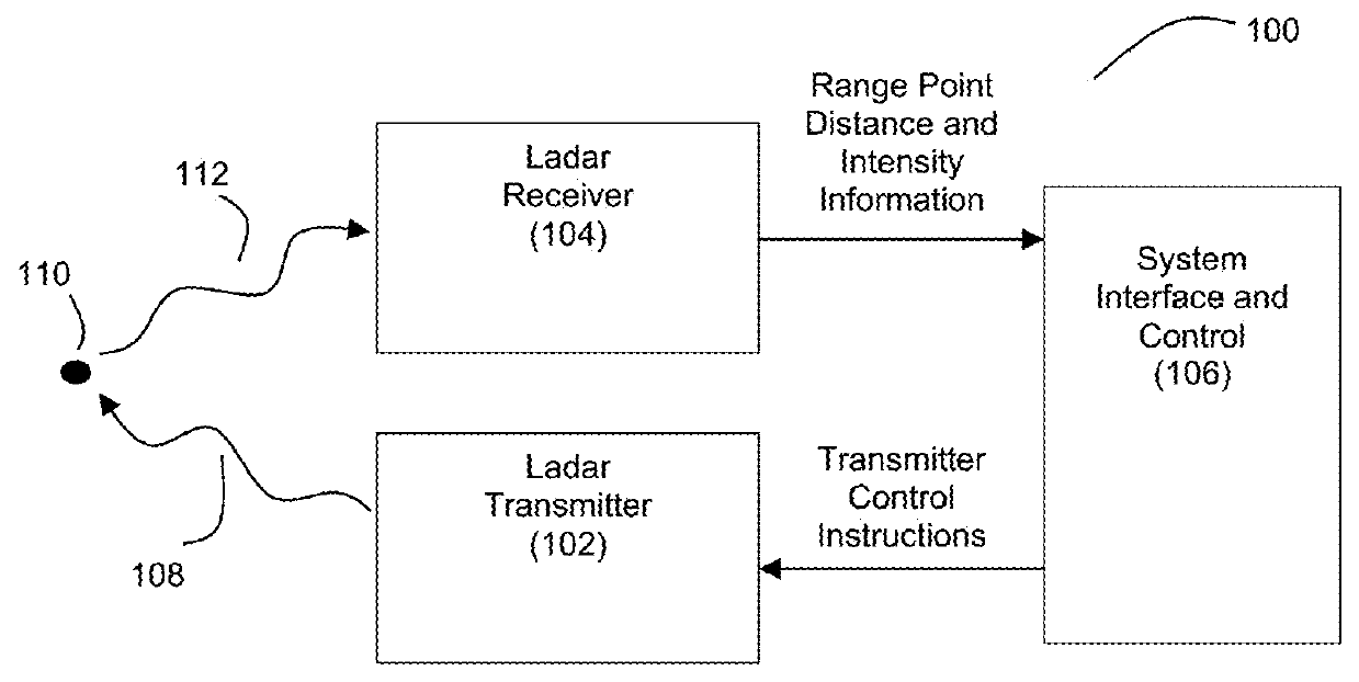
[0039]FIG. 1A illustrates an example embodiment of a ladar transmitter / receiver system 100. The system 100 includes a ladar transmitter 102 and a ladar receiver 104, each in communication with system interface and control 106. The ladar transmitter 102 is configured to transmit a plurality of ladar pulses 108 toward a plurality of range points 110 (for ease of illustration, a single such range point 108 is shown in FIG. 1A). Ladar receiver 104 receives a reflection 112 of this ladar pulse from the range point 110. Ladar receiver 104 is configured to receive and process the reflected ladar pulse 112 to support a determination of range point distance [depth] and intensity information. In addition the receiver 104 determines spatial position information [in horizontal and vertical orientation relative to the transmission plane] by any combination of (i) prior knowledge of transmit pulse timing, and (ii) multiple detectors to determine arrival angles.

[0040]In example embodiments, the la...


PUM


Abstract

Disclosed herein is a scanning ladar transmitter that employs an optical field splitter / inverter to improve the gaze characteristics of the ladar transmitter on desirable portions of a scan area. Also disclosed is the use of scan patterns such as Lissajous scan patterns for a scanning ladar transmitter where a phase drift is induced into the scanning to improve the gaze characteristics of the ladar transmitter on desirable portions of the scan area. Also disclosed is a compact beam scanner assembly that includes an ellipsoidal reimaging mirror.

Description

CROSS-REFERENCE AND PRIORITY CLAIM TO RELATED PATENT APPLICATIONS[0001]This patent application is a continuation-in-part of U.S. patent application Ser. No. 15 / 431,065, filed Feb. 13, 2017 and entitled “Ladar Transmitter with Optical Field Splitter / Inverter for Improved Gaze on Scan Area Portions”, which claims priority to (1) U.S. provisional patent application 62 / 297,126, filed Feb. 18, 2016 and entitled “Improved Ladar Transmitter with Resonant Scan Optical Field Splitter / Inverter” and (2) U.S. provisional patent application 62 / 439,378, filed Dec. 27, 2016 and entitled “Ladar Transmitter with Improved Gaze on Scan Area Portions”, the entire disclosures of each of which are incorporated herein by reference.[0002]This patent application is also a continuation-in-part of U.S. patent application Ser. No. 15 / 431,096, filed Feb. 13, 2017 and entitled “Ladar Transmitter with Induced Phase Drift for Improved Gaze on Scan Area Portions”, which claims priority to (1) U.S. provisional paten...

Claims


Application Information

Patent Timeline
Patent Type & Authority Patents(United States)
IPC IPC(8): G02B26/10G02B26/08G02B27/12G01S7/481
CPCG02B26/101G01S7/4814G02B27/126G02B26/0833G01S7/4817G01S17/42G01S7/497G02B27/14G02B27/141
Inventor DUSSAN, LUIS CARLOSDEMMER, DAVID R.STOCKTON, JOHNSTEINHARDT, ALLANCOOK, DAVID
Owner AEYE INC
Why Eureka
Try Eureka