Micro-energy harvester for battery free applications

a micro-energy and battery-free technology, applied in the direction of electric vehicles, electric variable regulation, instruments, etc., can solve the problems of not being useful, not being useful, and micro-energy applications currently not including cell phones, laptops, or other devices, so as to improve conversion efficiency, and avoid large startup current draws

Inactive Publication Date: 2018-08-07
TIEFNIG EUGEN
View PDF17 Cites 7 Cited by
  • Summary
  • Abstract
  • Description
  • Claims
  • Application Information

AI Technical Summary

Benefits of technology

[0014]An advantage of the present invention is the micro-energy harvester works with very low power sources, for example, as low as 100 nanowatts. This is achieved by an inductor in series with a normally off transistor as part, or also referred to as, an oscillator to slowly bring the input voltage at the transistor to a voltage threshold to turn the transistor on (e.g., about 100 millivolts), where 60 millivolts from a micro-energy source plus an induced voltage (e.g., 40 millivolts) at the input gives the threshold voltage required to start up (i.e., switch on) a transistor. The micro-energy harvester works with weak energy sources, such as a small (2 cm2) solar cell. The micro-energy harvester uses the drain to source leakage current from its input transistor at zero gate voltage to initiate oscillation at startup. After a few oscillations with the gate voltage amplitude steadily increasing, the drain source resistance reaches its on state value and current from the micro-energy source can flow. This method prevents the output voltage from a weak micro-energy source from collapsing due to excessive current draws at oscillator startup.
[0015]Other micro-energy harvesters use a J-FET as their input transistor, which is on at zero gate voltage. This means that at the moment an input source is connected, current can flow and, without oscillation, a large current will pass through the inductor, initially collapsing the source voltage. In the current invention, a different circuit topology is used with a MOSFET type of pass transistor, avoiding large startup current draws from weak energy sources and, at the same time, matching the internal resistance of weak energy sources for a more efficient conversion.
[0016]Another advantage of the present invention is the tight internal resistance matching with weak energy sources like solar cells at low light levels, which increases conversion efficiency at low light levels. The presented micro-energy harvester achieves conversion efficiencies up to 50% at low light levels which increase to 60% in bright sun light, compared to the approximately 20 to 30% efficiency for conventional micro-energy harvesters.
[0017]A further advantage of the present invention is that it is a complete and simple solution providing a unique conversion circuit combined with a charging and energy supervisory circuit. The power supervisor (manager) automatically starts up the application circuit once sufficient energy has accumulated, and shuts it down in case the working voltage is too low.

Problems solved by technology

The electrical equivalent of the input energy that a micro-energy harvester receives is in most cases below the thresholds of electronics and would not be useful absent the micro-energy harvester.
For example, a supply voltage of less than 0.7 Volt at an input of a transistor or diode is below the threshold that a transistor or diode needs to be turned on, and therefore would not be useful absent some form of transformation.
Thus, micro-energy applications currently do not include cell phones, laptops, or other devices requiring a battery or conventional power supplies because these applications require continuous power.
A problem with conventional micro-energy harvesters is that they require more operating power than some micro-energy sources can provide.
Another problem with conventional micro-energy harvesters is that they have low conversion efficiency.
Normally-on circuits draw high input current at start-up, making it impossible to use weak energy sources like small solar cells.
This problem exists because, prior to embodiments disclosed in this application, no one has discovered an improved micro-energy harvester with circuitry that can switch on when normally off (that is, turn it on when it is not already on to start with).
A further problem with conventional micro-energy harvesters is that they are not a complete solution.
Conventional micro-energy harvesters lack circuitry that allows them to charge a storage element like a small rechargeable battery or super capacitor.
Another problem with most conventional micro-energy harvesters is that they do not contain circuitry for their state of charge, which requires a power supervisory circuit.
However, Pollak's smaller turn on voltage still requires a large input current (and thus a larger startup power), has no circuit for charging an energy storage element and no power supervisory function.

Method used


Image

  • Micro-energy harvester for battery free applications
  • Micro-energy harvester for battery free applications
  • Micro-energy harvester for battery free applications

Examples


Embodiment Construction

[0025]Further features and advantages of the invention, as well as the structure and operation of various embodiments of the invention, are described in detail below with reference to the accompanying FIGS. 1-5, wherein like reference numerals refer to like elements.

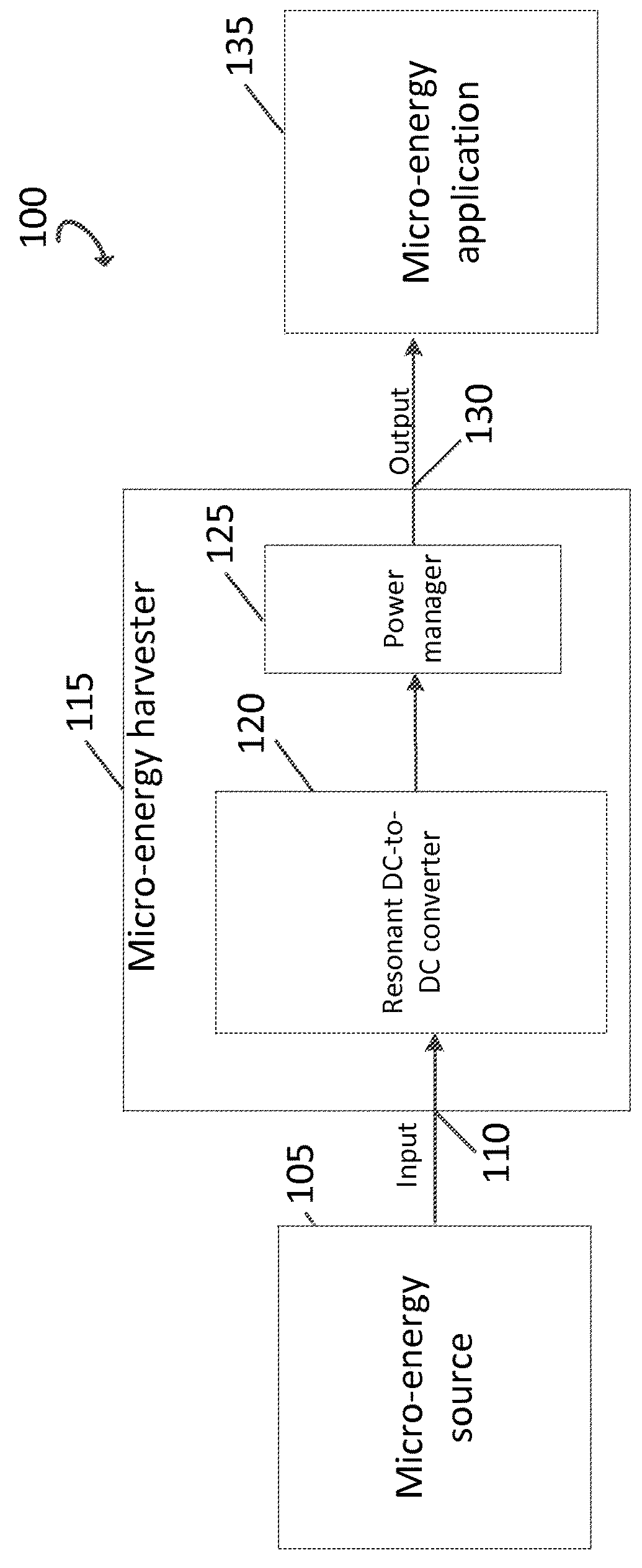
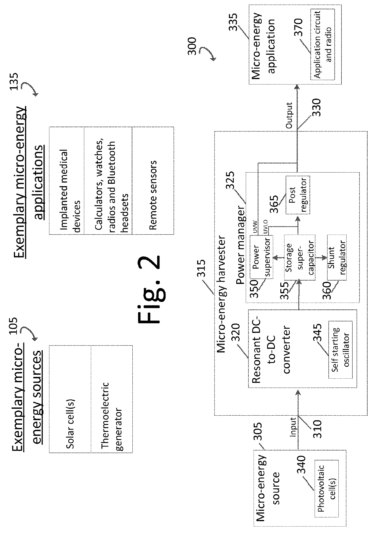
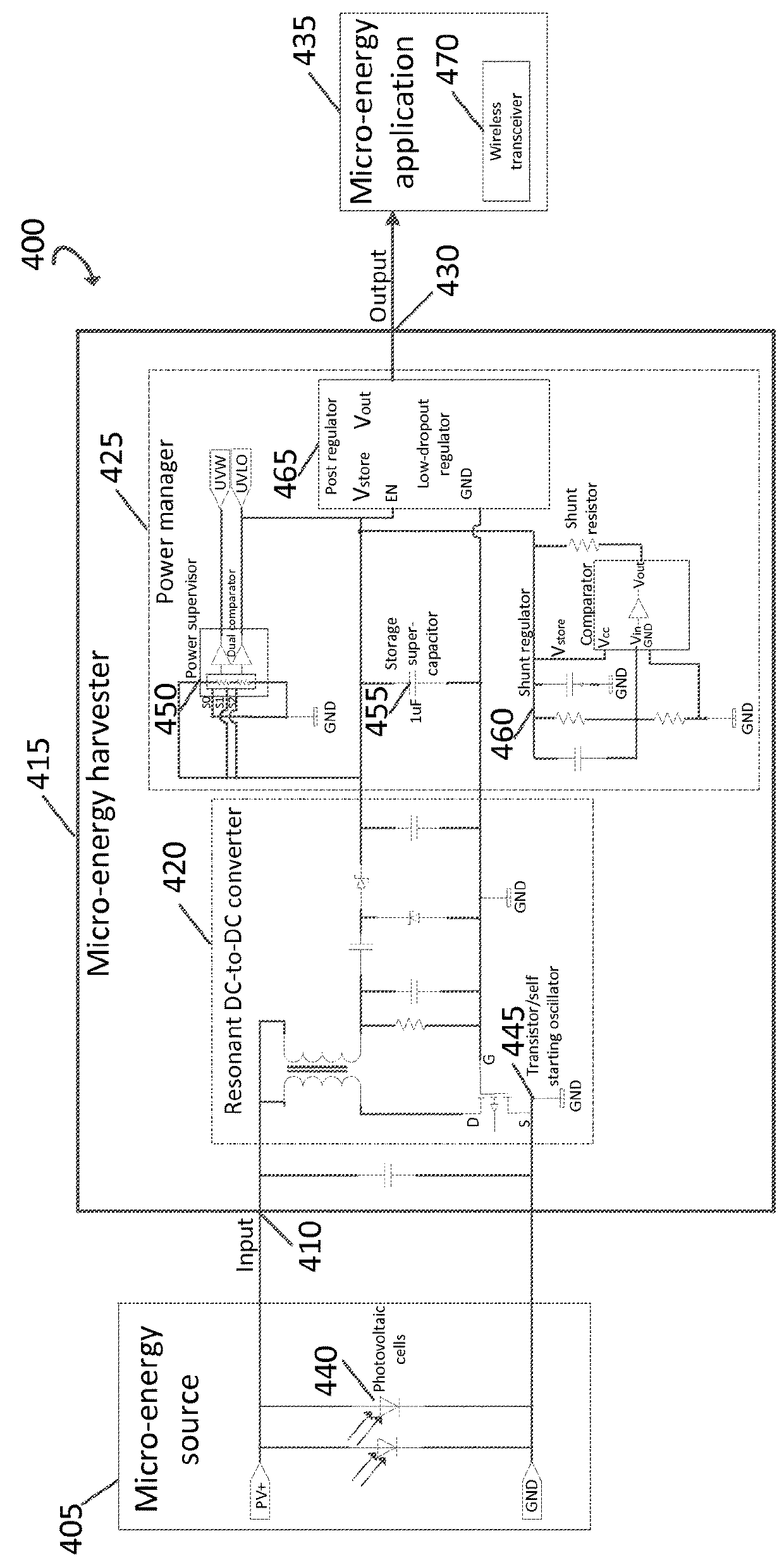
[0026]Although the micro-energy harvester is at times illustrated and described as being separate from the micro-energy source, the power manager, and micro-energy application, in some embodiments all of these are together on one circuit board. Additionally, although the invention is at times described and illustrated as working with a particular micro-energy source as the input power, such as a solar cell, the micro-energy harvester can work with other micro-energy input power source in other embodiments (e.g., a thermoelectric generator).

[0027]Embodiments of the present invention provide an electronic circuit to harvest and store energy from micro-energy sources such as small solar cells or other environmental low ener...


PUM


Abstract

A micro-energy harvester that receives an input direct current (DC) voltage from a micro-energy source. The micro-energy harvester includes an oscillator and builds up the input DC voltage into an output DC voltage, where the oscillator includes a transistor that is configured to be normally off and the transistor is configured to be switched on by the micro-energy source. The micro-energy harvester outputs the output DC voltage to a micro-energy application. The micro-energy application and the micro-energy harvester are both configured to operate without a battery. The micro-energy harvester also includes an integrated power manager that provides a complete solution for transforming and storing electrical energy from micro-energy power sources to efficiently power applications that do not require continuous power.

Description

BACKGROUND OF THE INVENTION[0001]1. Field of Invention[0002]The invention relates generally to micro-energy harvesters, and more particularly, to an improved micro-energy harvester that works with a lower input power source and works at a higher efficiency.[0003]2. Description of Related Art[0004]Energy harvesting, also known as power harvesting or energy scavenging, is the process by which energy is input from external input sources (e.g. solar power converting ambient energy into electrical energy, thermal energy, wind energy, salinity gradients, and kinetic energy) that are captured, built up, and stored for and delivered to small, wireless autonomous applications, like those used in wearable electronics and wireless sensor networks.[0005]A micro-energy source has very low power, which is fed into a micro-energy harvester. Micro-energy sources include environmental low energy DC or AC power generators and anything else that can output a low DC or AC power to a micro-energy harves...

Claims


Application Information

Patent Timeline
Patent Type & Authority Patents(United States)
IPC IPC(8): H02M3/338H02J7/35H02J7/34
CPCH02J7/35H02J7/345
Inventor TIEFNIG, EUGEN
Owner TIEFNIG EUGEN
Why Eureka
Try Eureka