Stormwater runoff separator and collector for curb inlet type catch basins

a technology of runoff separator and collector, which is applied in the direction of runoff/storm water treatment, treatment involving filtration, and the nature of treatment water, etc. it can solve the problems of significant environmental problems, untreated stormwater can have detrimental effects on receiving bodies, and the device as designed is not intended to be retrofitted into an existing structure, etc., to achieve the effect of facilitating a secondary outfall

Active Publication Date: 2018-08-28
MARSHALL AINSWORTH
View PDF15 Cites 5 Cited by
  • Summary
  • Abstract
  • Description
  • Claims
  • Application Information

AI Technical Summary

Benefits of technology

[0018]The general field of this invention applies to road structure, process, or apparatus street, or curb inlet for surface drainage. The invention is designed to intercept stormwater runoff at a curb-inlet type drainage-chambers. Interception is accomplished in such a way as to permit excess liquid beyond the capacity of the invention, and large debris, to be directed autom

Problems solved by technology

Untreated stormwater can have detrimental impacts on receiving bodies.
Urban municipalities have recognized that stormwater pollution, particularly the first flush, is a significant environmental problem.
This device as de

Method used


Image

  • Stormwater runoff separator and collector for curb inlet type catch basins
  • Stormwater runoff separator and collector for curb inlet type catch basins
  • Stormwater runoff separator and collector for curb inlet type catch basins

Examples


Embodiment Construction

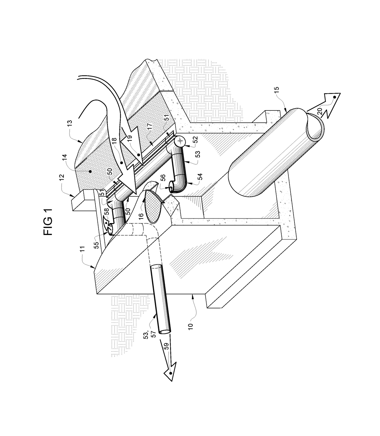
[0053]A preferred embodiment of the invention is shown in FIG. 1 where the installation relationship between the invention, the catch basin 10, the catch basin top 11, the curb 12, and the curb inlet 17 is shown. Approaching stormwater runoff 18 and 19 flows along the roadway 13 to the gutter pan 14 to the curb inlet 17 of the catch basin 10.

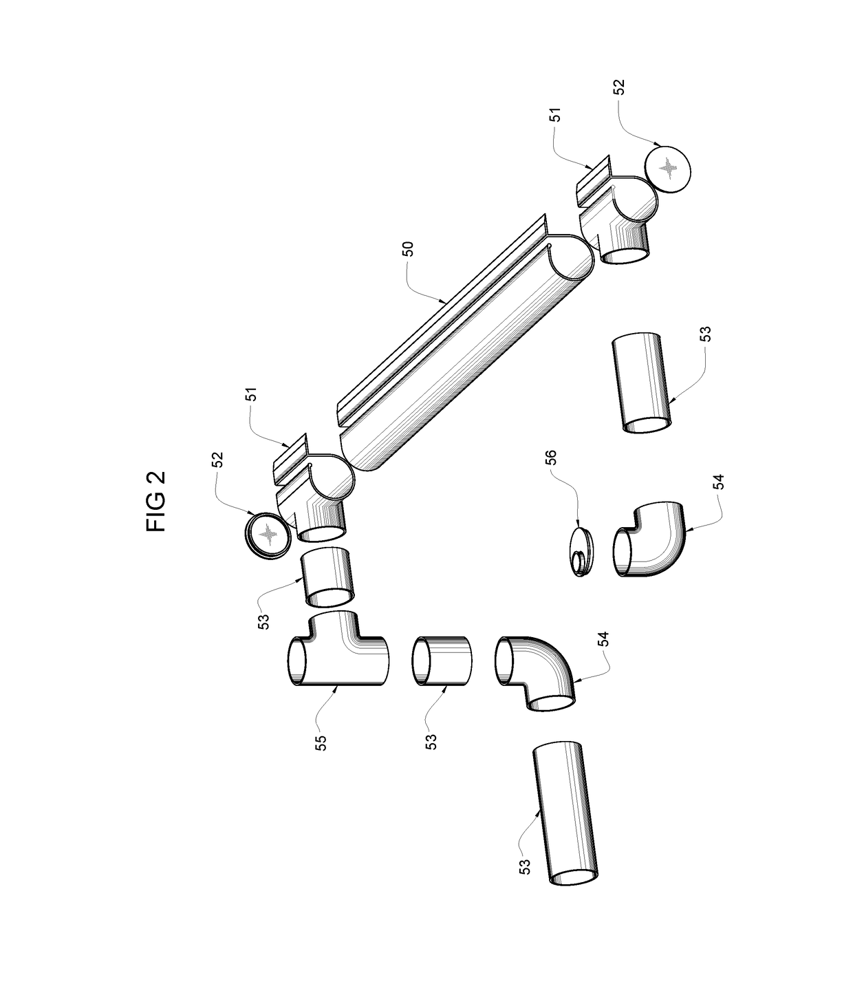
[0054]The preferred embodiment of the invention shown is installed along the front wall of the catch basin 10 at the curb inlet 17. The installation location allows for hydraulic separation of flows without impediment. The initial stormwater runoff 19 flows directly to the collection channel 50. Debris and excessive stormwater 18 flows into the existing catch basin 10. The method of attaching the collection channel 50 to the catch basin10 may vary depending on the orientation and material of the existing catch basin 10. Fasteners, and adhesives may be considered as appropriate attachment methods. Additional support brackets may be needed to secu...


PUM


Abstract

A hydraulic separation and collection system applicable to linear street curb-inlet type drainage-chambers, independent or connected to a storm drainage network. The FIRST FLUSH COLLECTOR™ is a pollutant separation and collection apparatus that can be integrated into an existing storm drain network, or be retrofitted as a component into a new or existing curb-inlet type drainage-chamber. The outfall from the FIRST FLUSH COLLECTOR™ can be redirected to a conventional stormwater pollutant BMP, or be diverted to a sanitary sewer, storm drain, or combined collection system for treatment downstream. The apparatus is envisaged as a simple, easy to install prefabricated-kit utilizing a basic build-in-place separation and collection apparatus. The apparatus can be readily adapted to the needs of a given curb-inlet type drainage-chamber with minor alterations to the chambers, or to the connected existing storm drainage network. The uniquely adaptative capability of the apparatus enables selective structuring based on the retrofitting requirements of a curb-inlet type drainage-chamber. The system is designed to handle a variety of ecosystem-contaminants, ranging from basic street-refuse and floatable objects, to coarse sediment, finer silt, and comparatively minute environmentally-hazardous petrochemicals, heavy-metals, phosphates, and nitrates. The system is design to refuse floatables and debris which will continue to the existing curb-inlet type drainage-chamber. Other pollutants contained in the first flush are readily collected from the apparatus and transferred to a selected outfall facility. The system has no moving or mechanical components and is designed to function on fluid hydraulic principles.

Description

CROSS-REFERENCE TO RELATED APPLICATIONS[0001]Not ApplicableSTATEMENT REGARDING FEDERALLY SPONSORED RESEARCH OR DEVELOPMENT[0002]Not ApplicableREFERENCE TO SEQUENCE LISTING, A TABLE, OR A COMPUTER PROGRAM LISTING COMPACT DISC APPENDIX (IF APPLICABLE)[0003]Not ApplicableBACKGROUND OF THE INVENTIONField of the Invention[0004]This invention relates to stormwater pollutant separator and collection apparatus; and more particularly it relates to said apparatus specifically adapted in a curb-inlet subterranean drainage-chambers to separate, collect and divert polluted stormwater runoff from roadways or other impervious surfaces with inlet structures.Background of the Invention[0005]Stormwater is conventionally defined as runoff generated from precipitation such as rain and snow melt. In developed areas runoff flows over impervious surfaces such as parking lots, streets, rooftops and paved areas as opposed to purculating into the soil as a natural means of pollutant removal and water filtrat...

Claims


Application Information

Patent Timeline
IPC IPC(8): E03F5/04E03F5/14C02F1/00E03F5/046C02F103/00
CPCE03F5/14C02F1/004E03F5/046E03F5/041C02F2103/001E03F2201/10E03F5/0402
Inventor MARSHALL, AINSWORTH
Owner MARSHALL AINSWORTH
Why Eureka
Try Eureka