
Coupling photovoltaic and concentrated solar power technologies for desalination

a technology of concentrated solar power and photovoltaic, which is applied in the direction of photovoltaics, lighting and heating apparatus, electrical apparatus, etc., can solve the problems of large thermal and electrical power consumption of msf for pumping, prior art systems and methods lack independence from electrical grid connection, and energy-intensive desalination technologies

Active Publication Date: 2018-09-04
SAUDI ARABIAN OIL CO
View PDF19 Cites 51 Cited by
  • Summary
  • Abstract
  • Description
  • Claims
  • Application Information

AI Technical Summary

Benefits of technology

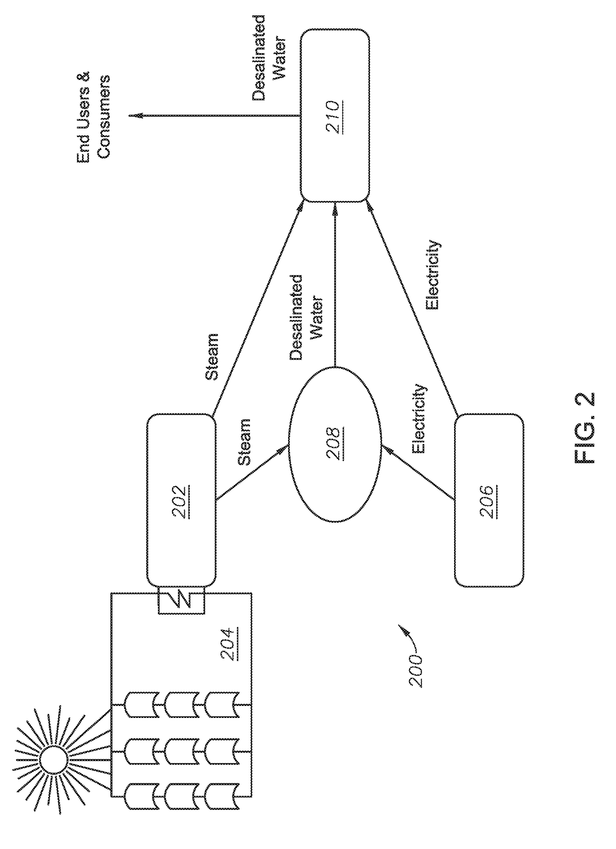
The present invention proposes a system and method for desalination using solar energy and steam from a concentrated solar power (CSP) system. The system does not require an electrical grid connection and can operate in a standalone configuration. The use of PV and CSP systems eliminates the need for input from fossil fuels and ensures only solar energy is used. The CSP system can provide heat to a multi-stage flash (MSF) desalination process, while the PV system can provide electricity to operate pumps and transport the desalinated water to consumers. The system can also store the product water in tanks for night use, adding flexibility to the plant and avoiding the need for power at night. Overall, the system offers lower cost and flexibility for desalination using solar energy.

Problems solved by technology

MSF consumes a large amount of thermal and electrical power for pumping.
Prior art systems and methods lack independence from electrical grid connections.
Even when prior art methods and systems are combined, such combinations still requires a grid connection to either transfer power to the grid or utilize power from the grid.
However, desalination technologies are energy intensive, requiring a large amount of electricity.

Method used


Image

  • Coupling photovoltaic and concentrated solar power technologies for desalination
  • Coupling photovoltaic and concentrated solar power technologies for desalination
  • Coupling photovoltaic and concentrated solar power technologies for desalination

Examples


Embodiment Construction

[0031]So that the manner in which the features and advantages of the embodiments of systems and methods for using combined PV and CSP technology for salt water desalination and transport, as well as others, which will become apparent, may be understood in more detail, a more particular description of the embodiments of the present disclosure briefly summarized previously may be had by reference to the embodiments thereof, which are illustrated in the appended drawings, which form a part of this specification. It is to be noted, however, that the drawings illustrate only various embodiments of the disclosure and are therefore not to be considered limiting of the present disclosure's scope, as it may include other effective embodiments as well.

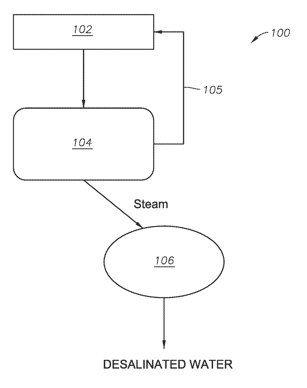
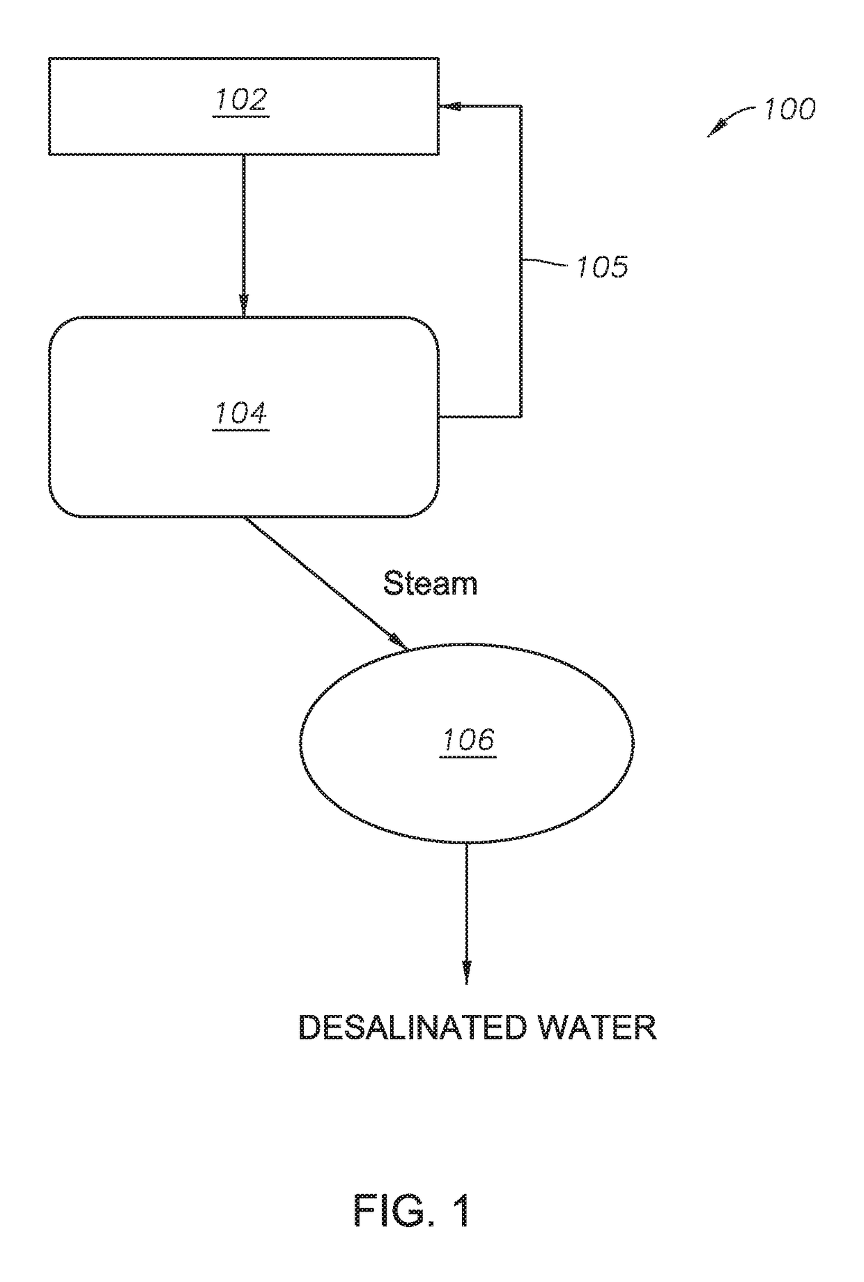
[0032]Referring now to FIG. 1, a process schematic is shown for producing desalinated water in one embodiment of the present disclosure. In combined CSP desalination system 100, a solar trough field 102 concentrates solar energy into a heat tran...


PUM

PropertyMeasurementUnit
pressureaaaaaaaaaa
temperatureaaaaaaaaaa
pressureaaaaaaaaaa

Abstract

Systems and methods for the desalination of water are disclosed. A system includes a concentrated solar power (CSP) system, the CSP system operable to concentrate solar energy to increase temperature and pressure of a heat transfer fluid and operable to produce steam utilizing heat from the heat transfer fluid; a photovoltaic (PV) system, the PV system operable to collect solar energy to produce electricity; a desalination system in fluid communication with the CSP system and in electrical communication with the PV system, the desalination system operable to produce desalinated water from a salt water source utilizing the steam from the CSP system and electricity from the PV system; and a pump station in fluid communication with the CSP system and the desalination system, and in electrical communication with the PV system, the pump station operable to transmit the desalinated water to consumers for use.

Description

BACKGROUND[0001]Field[0002]Embodiments of the disclosure relate to systems of and methods for using combined photovoltaic (PV) and concentrated solar power (CSP) technologies. In particular, embodiments relate to using combined PV and CSP technologies for autonomous water treatment, including desalination, and autonomous water transport to remote areas.[0003]Description of the Related Art[0004]Solar power plant technologies can be divided into two main groups: PV power plants, which use photovoltaic modules to convert solar irradiation directly into electricity, and solar thermal power plants, which generate electricity indirectly, via intermediate conversion into heat and mechanical energy. Solar power plants can also be divided into concentrating and non-concentrating systems. Concentrating solar thermal power plants, also known as concentrated solar power (CSP), produce electric power by first converting the sun's energy into high temperature heat using various mirror configurati...

Claims


Application Information

Patent Timeline
Patent Type & Authority Patents(United States)
IPC IPC(8): C02F1/06C02F1/44B01D61/10B01D1/28C02F1/14B01D61/02B01D1/00B01D3/14B01D3/06C02F1/04H01L31/04F22B1/00F03G6/06C02F103/08
CPCF24S20/30B01D1/0035B01D1/28B01D3/065B01D3/146B01D61/025B01D61/10C02F1/041C02F1/06C02F1/441C02F1/14H01L31/04B01D2313/365C02F2103/08C02F2201/009C02F2303/10F03G6/06F03G6/067F22B1/006Y02E10/46H02S40/44Y02W10/30Y02A20/142Y02A20/131Y02A20/212Y02E10/50Y02E10/60Y02A20/124F03G6/063F03G6/061
Inventor ALSHAHRANI, YAZEED SAFAR
Owner SAUDI ARABIAN OIL CO
Learn More