Automatic pellet loader of pneumatic air gun

a pneumatic air gun and pellet loader technology, applied in the direction of compressed gas guns, white arms/cold weapons, weapons, etc., can solve the problem of low loading accuracy, and achieve the effect of easy portability, accurate introduction, and reliable mounting

Active Publication Date: 2018-09-04
ZHONG SHAN NEW SWAN TECH CO LTD
View PDF14 Cites 13 Cited by
  • Summary
  • Abstract
  • Description
  • Claims
  • Application Information

AI Technical Summary

Benefits of technology

[0010]1. The pellet clip seat and the pellet clip lid are connected to form a magazine case. A pellet inlet is formed at the upper end of the magazine case. The pellet clip closure is rotatably connected to the magazine case for opening or closing of the pellet inlet. Such a structural design enables a large number of pellets to be stored in a standalone magazine case, thereby making it easy to be carried. Meanwhile, a pellet clip closure with resistance is used to close the pellet inlet, so that the pellets cannot drop out easily.
[0011]2. The bottom side wall of the pellet clip seat is provided with a loading sleeve that extends to the pellet clip lid. A center hole of the loading sleeve perpendicularly penetrates through the pellet clip seat, and the pellet clip lid comprises a loading channel allowing the pull-bolt thimble to pass through. The loading sleeve comprises an opening at the end thereof close to the pellet inlet side through which a single pellet can slip autonomously into the loading channel. The bottom of the loading channel comprises a shaft bore which communicates with the loading channel. The shaft bore is close to the opening. The magnetic shaft is tightly fitted in the shaft bore. The magnetic shaft is a magnet shaft which can magnetically attract a steel pellet entering the loading channel through the opening to the top end thereof. An upper end of the magnetic shaft is flush with an upper edge of the shaft bore or hidden inside the shaft bore. With regard to introduction of a pellet, such a structural design enables a pellet to enter the loading channel autonomously under its own weight. Also, since only one pellet can be introduced at a time and is positioned through the magnetic shaft which is a highly magneto-optical shaft, the pellets can be introduced accurately.
[0012]3. The bottom of the magazine case is provided with an inverted T shaped connector that comprises a clamping edge protruding outward at both sides of its bottom. The bottom of the groove is provided with a connector slot capable of mating to the connector. Both side walls of the connector slot are provided with a concave bayonet. One of the side clamping edges of the connector can be inserted into one of the side bayonets at an angle. The other side clamping edge of the connector can be folded down to be clamped in the other bayonet to achieve clamping connection of the magazine. With a structural design in which the T shaped connector mates to the connector slot, the magazine can be mounted reliably.
[0013]4. The bottom end of the connector is provided with a positioning block protruding downward at one end thereof. The bottom of the connector slot is provided with a positioning counterbore capable of mating to the positioning block. The positioning block protrudes into the positioning counterbore when the magazine is fully clamped into the connector slot. The use of a protruding positioning block for positioning can prevent reversed installation and can allow reliable positioning.

Problems solved by technology

Typically, the steel pellets of air guns are loaded to the barrel manually, leading to relatively low loading accuracy.

Method used


Image

  • Automatic pellet loader of pneumatic air gun
  • Automatic pellet loader of pneumatic air gun
  • Automatic pellet loader of pneumatic air gun

Examples


Embodiment Construction

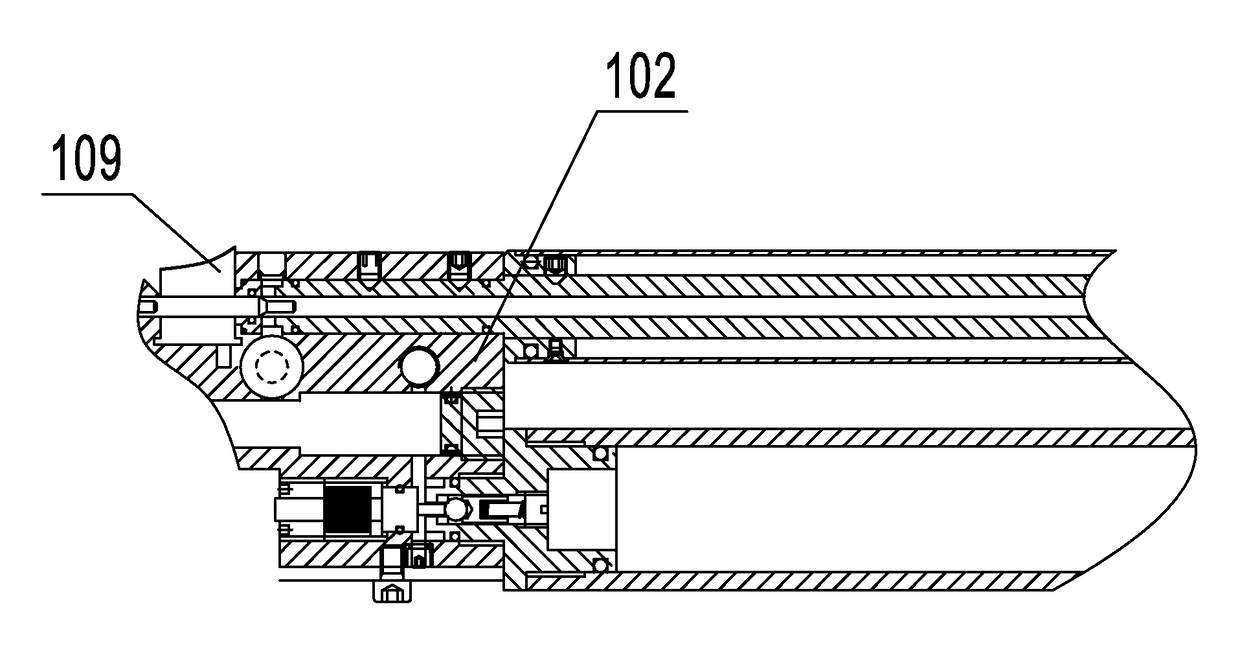
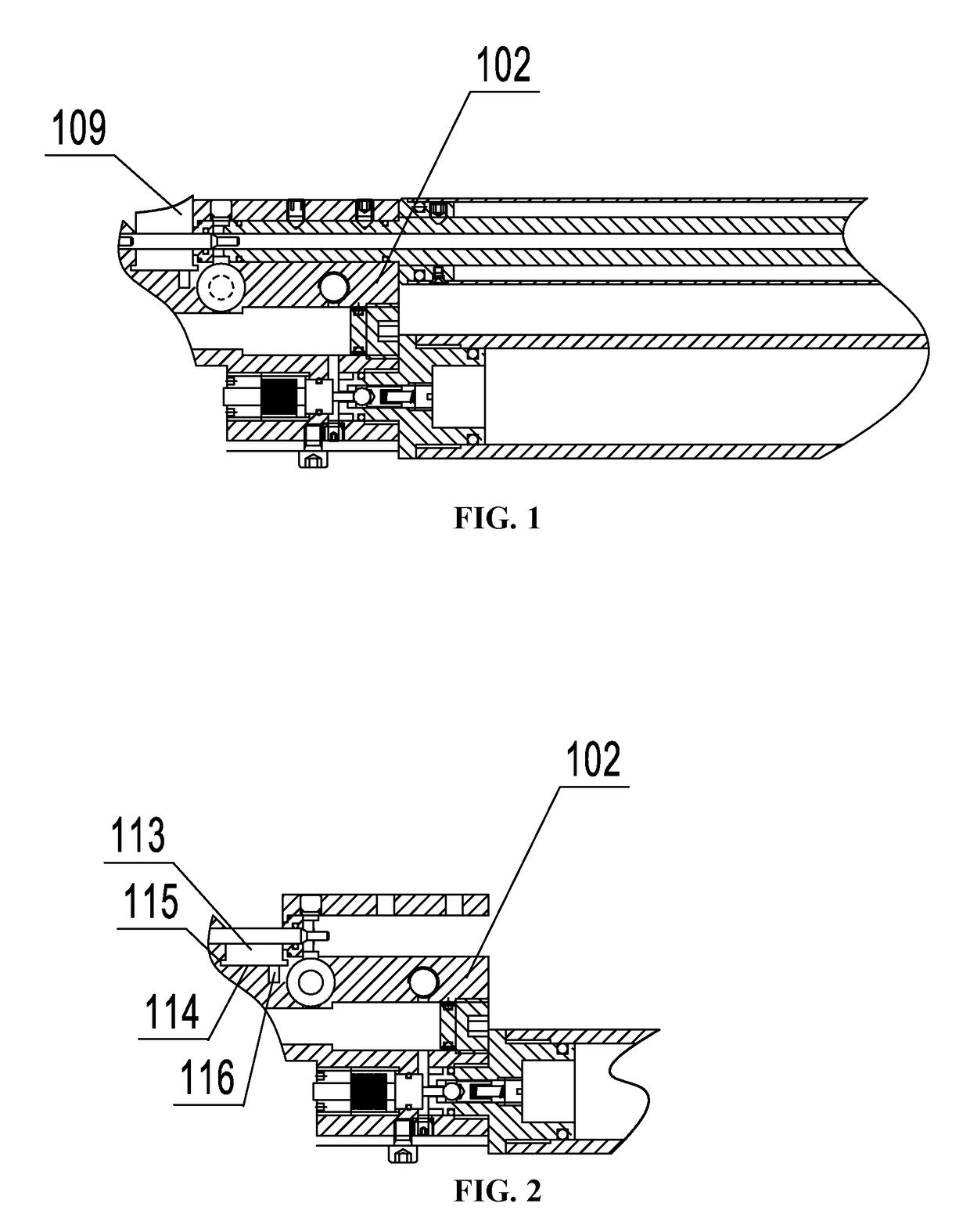
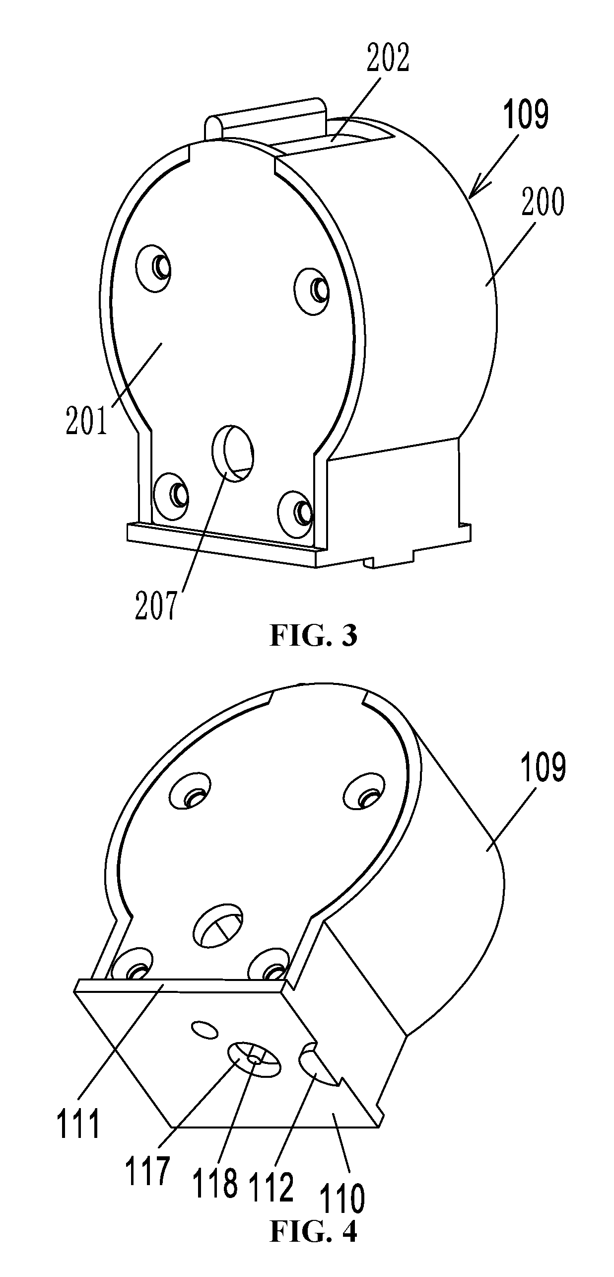
[0021]As shown in FIGS. 1, 2, 3, 4, 5, and 6, an automatic pellet loader of a pneumatic air gun which is detachably connected to a valve body 102 comprises a pellet clip seat 200, a pellet clip lid 201, a pellet clip closure 202, and a magnetic shaft (not shown). The pellet clip seat 200 and the pellet clip lid 201 are interlocked through a screw to form a magazine case 109 of a pellet loader. A pellet inlet 210 is formed at the upper end of the magazine case 109. The pellet clip closure 202 is rotatably connected to the magazine case for opening or closing of the pellet inlet 210. In this embodiment, a fold edge 204 is provided at the inner bottom wall of the pellet clip seat 200. A positioning slot is formed between the fold edge 204 and the inner wall of the pellet clip seat 200. The pellet clip closure 202 comprises a handle 205. When the pellet clip closure 202 is rotated to close the pellet inlet 210, the edge of the pellet clip closure 202 is inserted in the positioning slot....


PUM


Abstract

An automatic pellet loader of a pneumatic air gun, including a pellet clip seat, a pellet clip lid, a pellet clip closure, and a magnetic shaft. The pellet clip seat and the pellet clip lid are connected to form a magazine case that includes a pellet inlet. The pellet clip closure is rotatably connected to the magazine case for opening or closing the pellet inlet. The bottom side wall of the pellet clip seat is provided with a loading sleeve that extends to the pellet clip lid. A center hole of the loading sleeve perpendicularly penetrates through the pellet clip seat. The pellet clip lid includes a loading channel allowing the pull-bolt thimble to pass through. The loading sleeve includes an opening close to an exit side of the loading channel through which a single pellet can slip autonomously into the loading channel.

Description

CROSS-REFERENCE TO RELATED APPLICATIONS[0001]This application is a continuation-in-part of International Patent Application No. PCT / CN2016 / 077181 with an international filing date of Mar. 24, 2016, designating the United States, and further claims foreign priority to Chinese Patent Application No. 201620040531.8 filed Jan. 15, 2016. The contents of all of the aforementioned applications, including any intervening amendments thereto, are incorporated herein by reference. Inquiries from the public to applicants or assignees concerning this document or the related applications should be directed to: Matthias Scholl P.C., Attn.: Dr. Matthias Scholl Esq., 245 First Street, 18th Floor, and Cambridge, Mass. 02142.BACKGROUND OF THE INVENTIONField of the Invention[0002]The present disclosure relates to an automatic pellet loader of a pneumatic air gun.Description of the Related Art[0003]Typically, the steel pellets of air guns are loaded to the barrel manually, leading to relatively low load...

Claims


Application Information

Patent Timeline
Patent Type & Authority Patents(United States)
IPC IPC(8): F41B11/50F41B11/54
CPCF41B11/54F41B11/50F41A9/84
Inventor ZHU, ZUOPENG
Owner ZHONG SHAN NEW SWAN TECH CO LTD
Why Eureka
Try Eureka