
Image series alignment system and method

a technology of image series and alignment system, applied in the field of image series alignment system and method, can solve the problems of poor image resolution, short penetration depth, and low amount of electron radiation applied to the object during each imaging time period

Active Publication Date: 2018-09-04
KING ABDULLAH UNIV OF SCI & TECH
View PDF7 Cites 2 Cited by
  • Summary
  • Abstract
  • Description
  • Claims
  • Application Information

AI Technical Summary

Benefits of technology

The patent describes a method and system for aligning and correcting images that are taken of an object and have spatial shifts between them. The method involves receiving a sequence of images, transforming them into a Fourier domain, calculating an amplitude filtered pattern based on the amplitudes of the transformed images, and determining the spatial shifts between consecutive images in the sequence. Using these shifts, the images are aligned and summed to create a corrected summed image that is free from spatial shifts. The technical effects of this invention are improved image accuracy and improved image quality, making it easier to inspect and analyze objects using image processing techniques.

Problems solved by technology

Some objects imaged as part of an HRTEM study, such as crystalline solids, are sensitive to and can be damaged by the electron beam, and thus the amount of electron radiation applied to the object during each imaging time period can be very low.
Although knock-on damage can be addressed using low accelerating voltages (e.g., 60-120 kV), the use of low-energy electrons results in poor image resolution and short penetration depth.
Applying a low amount of electron radiation using a short exposure results in each individual image in the sequence of images being very noisy, so much so that it is often difficult to observe the object in any single image.
It is quite common, and typically unavoidable, that the object moves or drifts during the imaging sequence, and thus the object will appear in different locations in different images in the sequence of images.
Although these techniques can improve some images, the techniques do not adequately address the low signal-to-noise ratio in images of electron-beam sensitive materials that are imaged using very short exposure times and low doses of electron beam radiation.

Method used


Image

  • Image series alignment system and method
  • Image series alignment system and method
  • Image series alignment system and method

Examples


Embodiment Construction

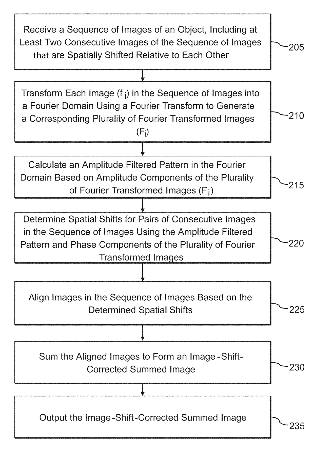
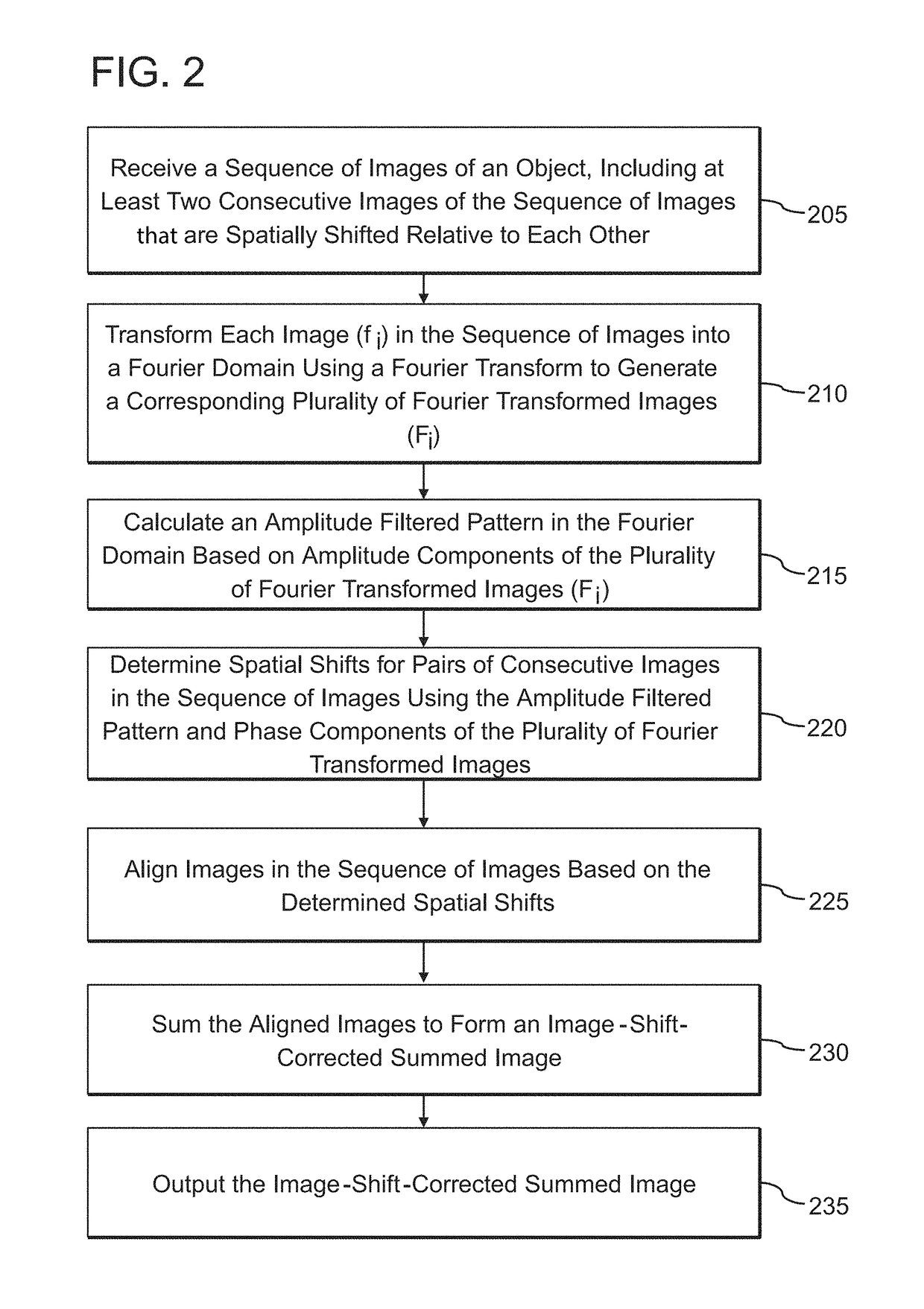
[0020]The following description of the exemplary embodiments refers to the accompanying drawings. The same reference numbers in different drawings identify the same or similar elements. The following detailed description does not limit the invention. Instead, the scope of the invention is defined by the appended claims. The following embodiments are discussed, for simplicity, with regard to the terminology and structure of high resolution transmission electron microscopy (HRTEM). However, the embodiments to be discussed next are not limited to HRTEM but may be applied to any type of image analysis requiring alignment of a series of images having relatively high signal-to-noise ratios, including image analysis for other types of microscopy, medical imaging, and computer vision.

[0021]Reference throughout the specification to “one embodiment” or “an embodiment” means that a particular feature, structure or characteristic described in connection with an embodiment is included in at leas...


PUM


Abstract

A system and method involve receiving a sequence of images of an object with at least two consecutive images of the sequence being spatially shifted relative to each other. Each image is transformed into a Fourier domain using a Fourier transform to generate a corresponding plurality of Fourier transformed images. An amplitude filtered pattern is calculated in the Fourier domain based on amplitude components of the plurality of Fourier transformed images. Spatial shifts for pairs of consecutive images in the sequence of images are determined using the amplitude filtered pattern. Images in the sequence of images are aligned based on the determined spatial shifts and the aligned images are summed to form an image-shift-corrected summed image.

Description

BACKGROUNDTechnical Field[0001]Embodiments of the subject matter disclosed herein generally relate to systems and methods for aligning a time series of images of an object.Discussion of the Background[0002]One type of device that uses an electron beam for imaging an object is a transmission electron microscope (TEM). TEMs are commonly used for high resolution transmission electron microscopy (HRTEM) to image crystalline solids consisting of periodically arranged atoms. An HRTEM study of an object, such as crystalline solids, typically involves taking a time series sequence of images of the object, each image being subject to a very short exposure time. Some objects imaged as part of an HRTEM study, such as crystalline solids, are sensitive to and can be damaged by the electron beam, and thus the amount of electron radiation applied to the object during each imaging time period can be very low. Some materials can be damaged by a cumulative electron dose of less than 10 electrons per ...

Claims


Application Information

Patent Timeline
Patent Type & Authority Patents(United States)
IPC IPC(8): G06T7/37
CPCG06T7/37G06T2207/10056G06T2207/20056G06T2207/10016G06T5/10G06T5/50G06T2207/20182
Inventor ZHANG, DALIANGHAN, YULI, KUNZHU, YIHAN
Owner KING ABDULLAH UNIV OF SCI & TECH
Learn More