Vehicle including electronic control unit configured to control inverter

a technology of electronic control unit and inverter, which is applied in the field of vehicles, can solve the problems of inability to execute the second pwm control, inability to control the second pwm, so as to reduce the responsiveness of the electric motor, and prevent an overcurrent or an overvoltage

Active Publication Date: 2018-09-25
DENSO CORP
View PDF14 Cites 11 Cited by
  • Summary
  • Abstract
  • Description
  • Claims
  • Application Information

AI Technical Summary

Benefits of technology

[0004]However, in the technique of generating pulse signals and outputting the pulse signals to the power conversion device in the above-mentioned vehicle, a period in which the pulse signals are generated is longer and responsiveness (trackability of an operating point when a target operating point changes) of the electric motor is lower in comparison with a technique of generating pulse signals by comparison of voltage commands of respective phases of the electric motor with a carrier voltage and outputting the pulse signals to the power conversion device. Accordingly, when an abnormality occurs in a voltage sensor or a current sensor, an overcurrent or an overvoltage is likely to occur in the inverter.
[0005]The disclosure provides a vehicle that can prevent an overcurrent or an overvoltage from occurring in an inverter.
[0007]In the vehicle according to the aspect, the control of the inverter is performed by switching the plurality of controls including the first PWM control and the second PWM control. The first PWM control is control of generating a first PWM signal by comparison of the voltage commands of respective phases based on the torque command of the motor with the carrier voltage and switching the plurality of switching elements of the inverter. The second PWM control is control of generating a second PWM signal based on a modulation factor of a voltage and a voltage phase based on the torque command of the motor and the number of pulses in a predetermined period of an electrical angle of the motor and switching the plurality of switching elements of the inverter. When an abnormality occurs in at least one of a current sensor detecting a current applied to the motor or a voltage sensor detecting a voltage of power supplied to the inverter, execution of the second PWM control is limited. In the second PWM control, a period in which the pulse signals are generated is longer and responsiveness of the electric motor is lower in comparison with the first PWM control. Accordingly, when an abnormality occurs in the voltage sensor or the current sensor, an overcurrent or an overvoltage is likely to occur in the inverter. As a result, it is possible to prevent an overcurrent or an overvoltage from occurring in the inverter by limiting execution of the second PWM control when an abnormality occurs in the voltage sensor or the current sensor. Here, the “limiting of execution of the second PWM control” includes reduction of an execution range of the second PWM control or prohibition of the second PWM control.
[0008]The vehicle according to the aspect may further include: a boost converter configured to boost a voltage of power from the battery and to supply the boosted voltage to the inverter; a second current sensor configured to detect a current flowing in the boost converter; and a second voltage sensor configured to detect a voltage of power supplied to the boost converter. The electronic control unit may be configured to limit execution of the second PWM control when an abnormality occurs in at least one of the second current sensor or the second voltage sensor. According to the aspect, it is possible to prevent an overcurrent or an overvoltage from occurring in the inverter in the vehicle according to the aspect including a boost converter. Here, the “limiting of execution of the second PWM control” may include an operation stop of the boost converter.

Problems solved by technology

Accordingly, when an abnormality occurs in a voltage sensor or a current sensor, an overcurrent or an overvoltage is likely to occur in the inverter.
When an abnormality occurs in at least one of a current sensor detecting a current applied to the motor or a voltage sensor detecting a voltage of power supplied to the inverter, execution of the second PWM control is limited.
Accordingly, when an abnormality occurs in the voltage sensor or the current sensor, an overcurrent or an overvoltage is likely to occur in the inverter.

Method used


Image

  • Vehicle including electronic control unit configured to control inverter
  • Vehicle including electronic control unit configured to control inverter
  • Vehicle including electronic control unit configured to control inverter

Examples


Embodiment Construction

[0014]Hereinafter, an embodiment of the disclosure will be described with reference to an example.

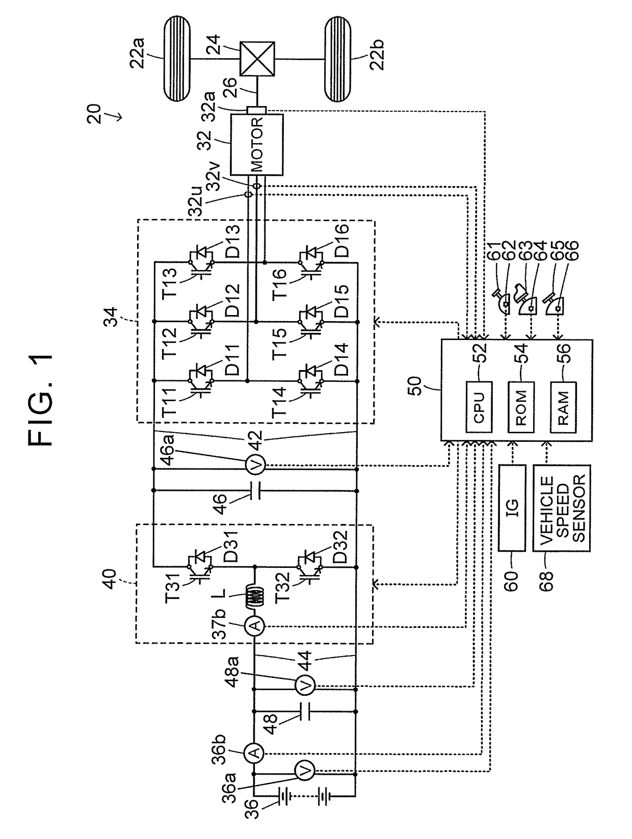
[0015]FIG. 1 is a diagram schematically illustrating a configuration of an electric vehicle 20 according to an embodiment of the disclosure. The electric vehicle 20 according to the embodiment includes a motor 32, an inverter 34, a battery 36, a boost converter 40, and an electronic control unit 50 as illustrated in the drawing.

[0016]The motor 32 is constituted by a synchronous generator-motor and includes a rotor in which a permanent magnet is embedded and a stator on which a three-phase coil is wound. The rotor of the motor 32 is connected to a drive shaft 26 which is connected to driving wheels 22a and 22b via a differential gear 24.

[0017]The inverter 34 is connected to the motor 32 and is also connected to the boost converter 40 via a high-voltage power line 42. The inverter 34 includes six transistors T11 to T16 and six diodes D11 to D16. The transistors T11 to T16 are arranged as ...


PUM


Abstract

A vehicle includes an electronic control unit configured to perform control of an inverter by switching a plurality of controls including: first PWM control of generating a first PWM signal of a plurality of switching elements by comparison of voltage commands of respective phases based on a torque command of a motor with a carrier voltage and switching the plurality of switching elements; and second PWM control of generating a second PWM signal of the plurality of switching elements based on a modulation factor of a voltage and a voltage phase based on the torque command and the number of pulses in a predetermined period of an electrical angle of the motor and switching the plurality of switching elements. The electronic control unit is configured to limit execution of the second PWM control when an abnormality occurs in at least one of the current sensor or the voltage sensor.

Description

CROSS-REFERENCE TO RELATED APPLICATIONS[0001]This application claims priority to Japanese Patent Application No. 2016-091163 filed on Apr. 28, 2016, the entire contents of which are hereby incorporated by reference.BACKGROUND1. Technical Field[0002]The disclosure relates to a vehicle and more particularly to a vehicle including a motor, an inverter, and a battery.2. Description of Related Art[0003]As such a type of vehicle, a vehicle which includes an electric motor and a power conversion device having an inverter circuit that drives the electric motor by switching a plurality of switching elements and in which pulse signals of the plurality of switching elements are generated based on the number of pulses in one electrical period of the electric motor and a modulation factor of a voltage and a voltage phase based on a torque command of the electric motor to switch the plurality of switching elements has been proposed (for example, see Japanese Patent Application Publication No. 201...

Claims


Application Information

Patent Timeline
Patent Type & Authority Patents(United States)
IPC IPC(8): H02P29/024H02M7/5387B60L11/18H02P27/08H02M1/32H02M1/088H02M1/00
CPCB60L11/1803H02M1/088H02M1/32H02P27/085H02P29/024H02M7/53871H02M2001/0009B60L50/51H02P29/0241H02M1/0009H02M1/325Y02T10/70
Inventor YAMADA, KENJIYAMAMOTO, TOSHIHIROMIZUNO, MASASHI
Owner DENSO CORP
Why Eureka
Try Eureka