
Downhole safety valve and method of application

a safety valve and safety technology, applied in the field of oil and gas drilling tools, can solve the problems that the safety valve cannot be operated downhole, and achieve the effects of cost-effective, cost-effective inspection, and more efficient inspection, maintenance, repair and replacemen

Active Publication Date: 2018-10-02
NEOP LLC
View PDF7 Cites 0 Cited by
  • Summary
  • Abstract
  • Description
  • Claims
  • Application Information

AI Technical Summary

Benefits of technology

The invention provides a way to save money and improve the inspection, maintenance, repair, and replacement of tools upstream of the BHA (the bottom hole assembly) in a string, by using Flapper-DSV combinations or profile nipple-DSV combinations. Even if tools are not placed at the BHA, these combinations can still be used to inspect, maintain, repair, or replace string sections upstream of the BHA. This invention also allows for efficient inspection, maintenance, repair, or replacement of string sections upstream of the BHA without the need for a wire line or tripping.

Problems solved by technology

A “DSV” is a valve which can be readily closed and opened once it is at the surface, but generally cannot be operated downhole.

Method used


Image

  • Downhole safety valve and method of application
  • Downhole safety valve and method of application
  • Downhole safety valve and method of application

Examples


Embodiment Construction

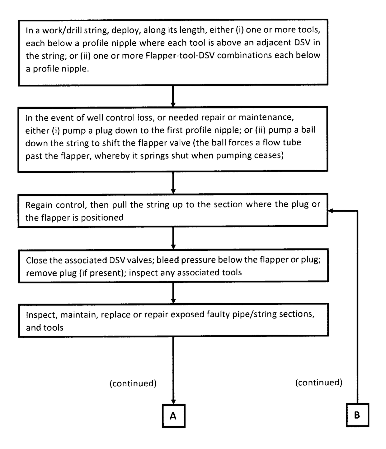
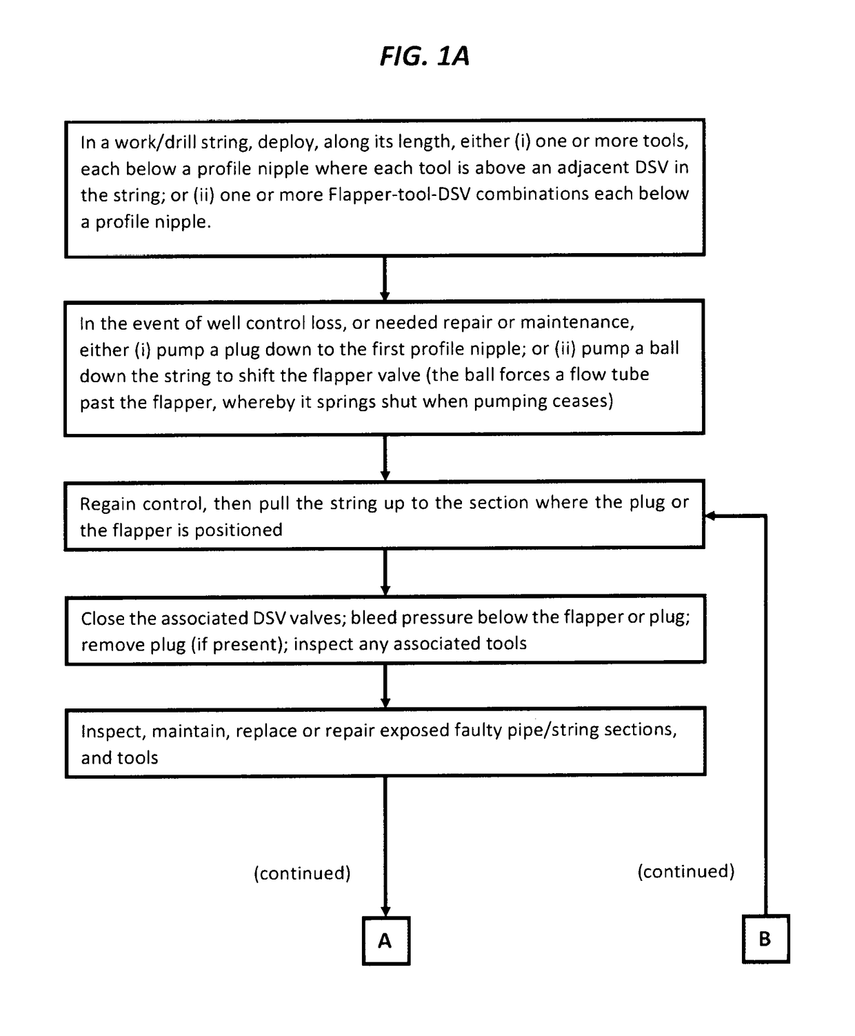
[0021]Referring to FIG. 1A, one preferably deploys one or more Flapper-tool-DSV combinations, with each preferably below a profile nipple, and where a tool 10 (as depicted in FIG. 4) is between each Flapper and DSV. When positioned in the string: the upper end 12 of tool 10 is joined (preferably by threading through adapters) onto the lower end 21 of flapper assembly 20 in FIGS. 2B and 2C; and the lower end 14 of tool 10 is threaded into the upper end 58 of DSV 40 in FIG. 3A. Unlike the position of upper valve 42 in FIGS. 3A and 3B, this valve 42, and valve 44, are open when DSV 40 is in position in the string during operations.

[0022]As noted in FIG. 1A, flapper assembly 20 is optional; one can rely on a profile nipple-plug with the tool 10 and DSV instead. One may also wish to deploy DSVs (associated with either a profile nipple-plug or flapper assembly 20) along the string, without an associated tool 10. If there is no tool 10 present, end 21 of flapper assembly 20 is joined direc...


PUM


Abstract

Disclosed is a cost-effective remedy to loss of well control caused by a defective string section upstream of the BHA, and more cost-effective inspection, maintenance, repair and replacement of any tools placed upstream of the BHA. The solution is to deploy one or more tools along the length of the string, either: (i) each tool below a profile nipple, and where each tool is upstream from an adjacent downhole safety valve (“DSV”); or (ii) one or more Flapper-tool-DSV combinations each below a profile nipple, and where the tool is positioned between each Flapper and DSV in the combination. If desired, the valving system described may be deployed along the string without a tool, to allow section-by-section inspection, maintenance, repair and replacement of string sections.

Description

BACKGROUND[0001]Conventionally, tools used in oil and gas drilling, particularly jarring devices (“jars” see e.g. U.S. Pat. Nos. 9,038,744; 8,151,910, respectively entitled: “Jet Hammer” and “Drilling Jar,” both incorporated by reference) were part of the bottomhole assembly (BHA). The BHA is at the lower-end of a drill-string (which is generically referred to as a work string, including both coil tubing and pipe strings; or, generically referred to as a “string” herein). The BHA consists of (from the bottom up in a vertical well) the drill bit, the drill bit sub, optionally, a mud motor (used for driving of the bit hydraulically without rotating the work string), as well as stabilizers, which keep the assembly centered in the hole, a drill collar (heavy, thick-walled tubes used to apply weight to the drill bit) and preferably jars and, as needed, crossovers (adaptors) for fitting together different threadforms on the various components.[0002]Directional drilling is now commonplace,...

Claims


Application Information

Patent Timeline
IPC IPC(8): E21B23/14E21B23/02E21B34/00E21B23/03E21B34/06E21B34/16E21B34/10
CPCE21B23/02E21B23/14E21B34/102E21B34/16E21B34/063E21B23/03E21B2034/002E21B2034/005E21B2200/04E21B2200/05E21B34/142
Inventor WOODS, JOSHUA SLADE
Owner NEOP LLC
Learn More