

Monitoring device, terminal, and monitoring system for monitoring the environment
a monitoring system and monitoring device technology, applied in the field of monitoring installation, can solve the problems of high infrastructure expenditure for the provision and operation of the plurality of measurement points, and the high cost of high requirements for spatially resolved insights on the distribution of radioactive radiation
- Summary
- Abstract
- Description
- Claims
- Application Information
AI Technical Summary
Benefits of technology
Problems solved by technology
Method used
Image

Examples
Embodiment Construction
[0004]Therefore, the invention is based on the object of creating a corresponding monitoring system with a significantly lower infrastructure expenditure.
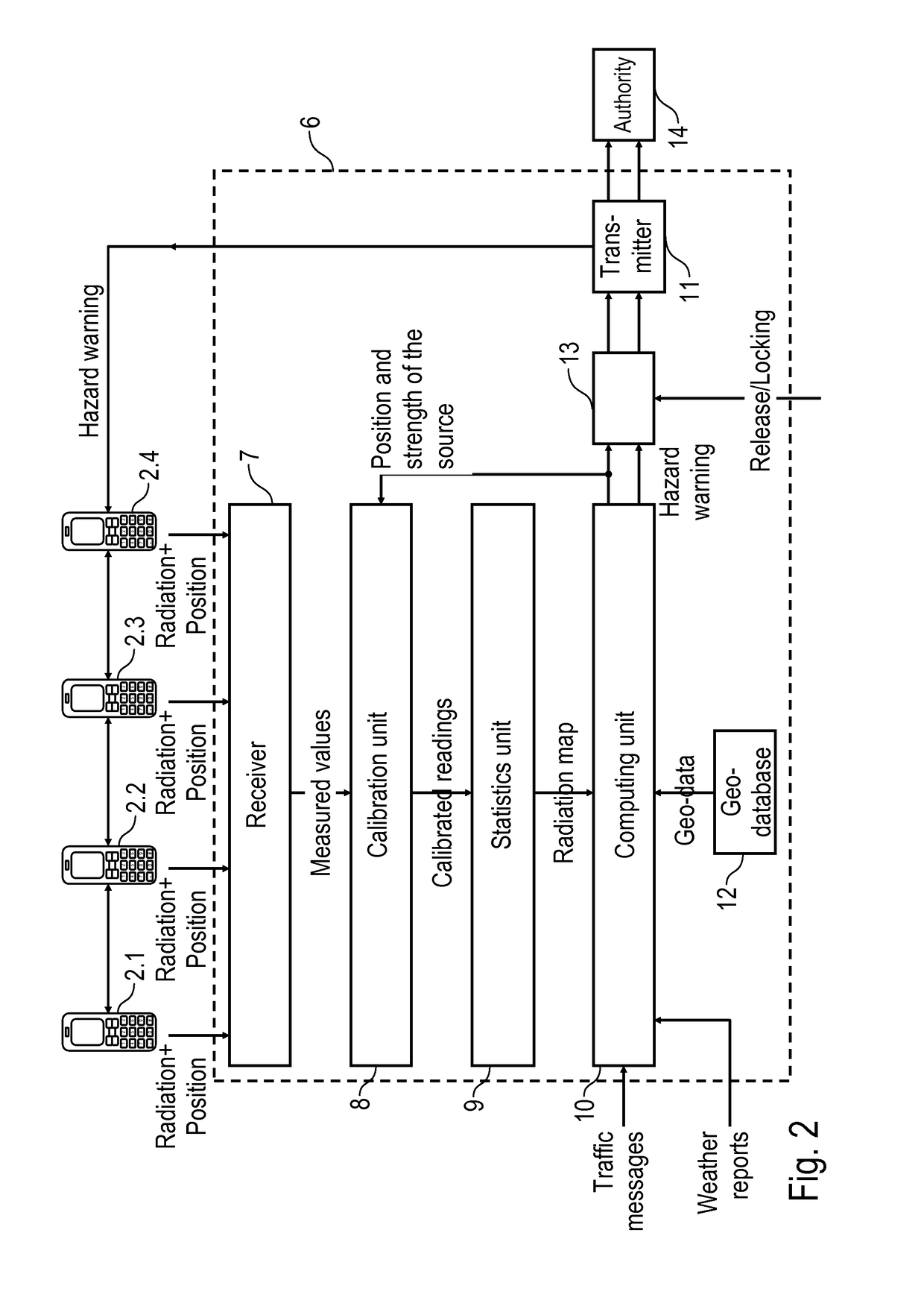
[0005]This object is solved by a monitoring installation (evaluation unit), in accordance with adapted terminal units (measurement points) and a monitoring system according to the claims.
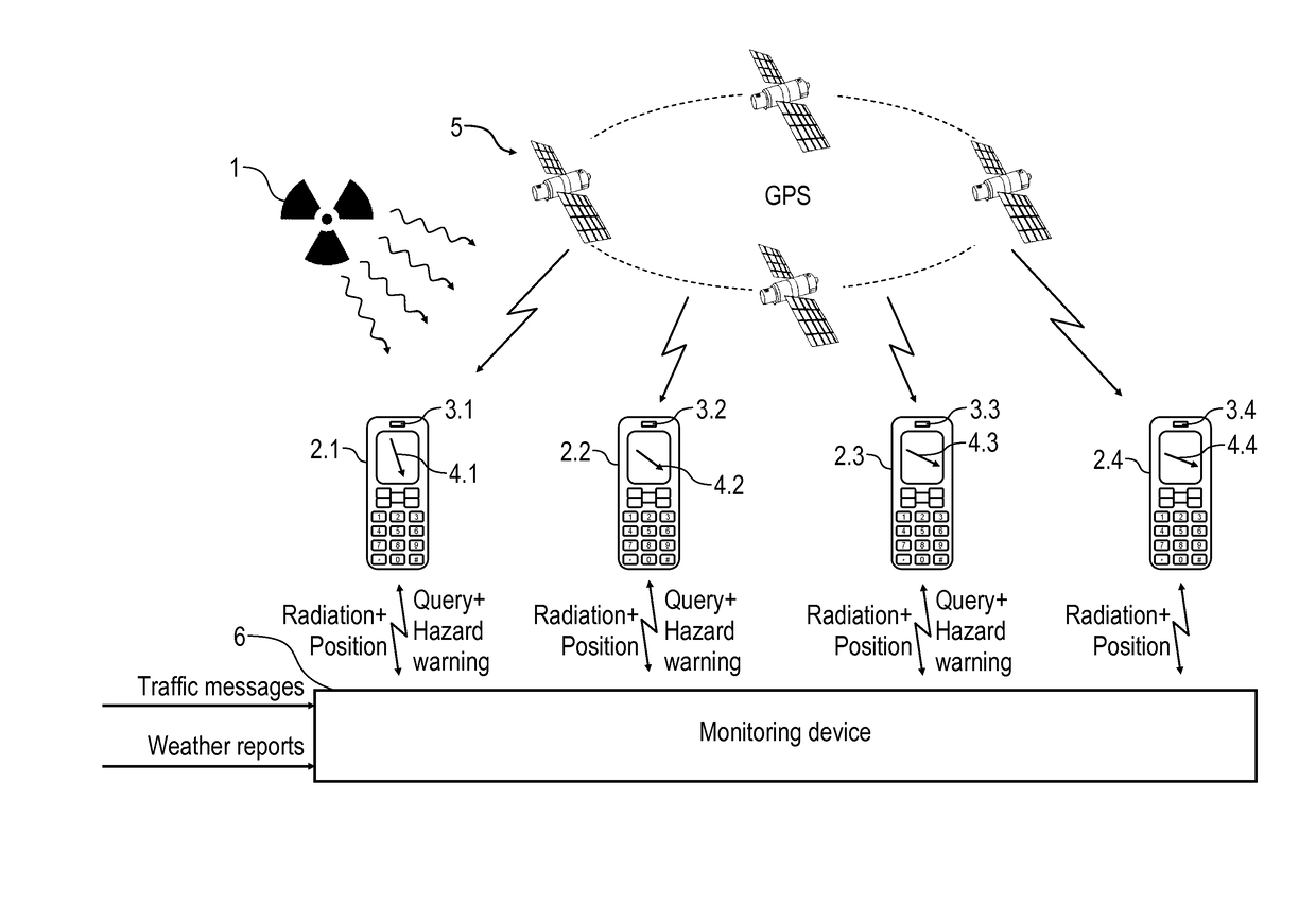
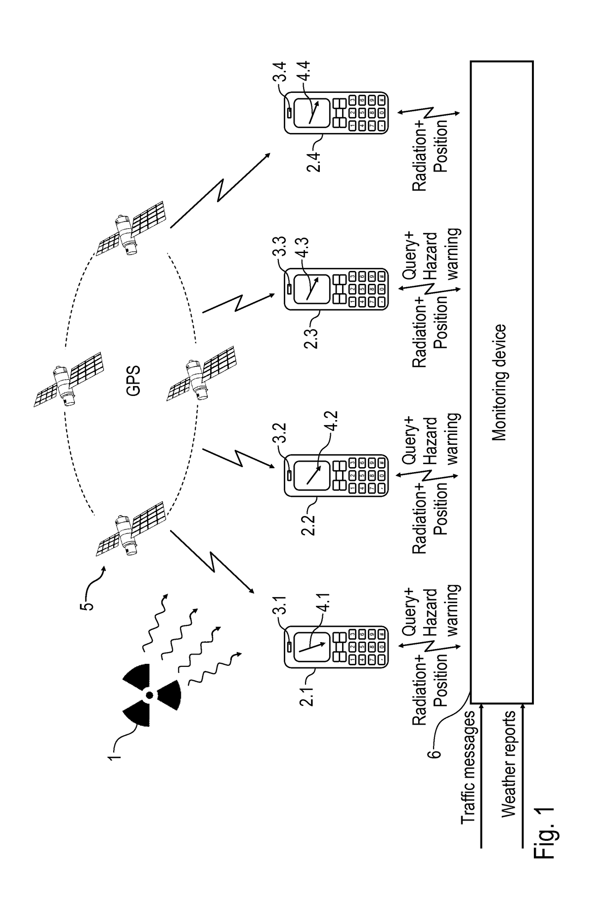
[0006]The invention is based upon the technical-physical insight that radioactive radiation can be measured not only by radiation sensors (e.g. Geiger-Müller counter tubes) specially designed for this purpose, but rather also by conventional image sensors (e.g. CCD sensors, CMOS sensors), which are included in digital cameras of modern terminal units (e.g. mobile phones, notebooks, laptops, etc.). The invention therefore provides that such image sensors in modern terminal units are also used for radiation measurement, which allows the establishment of a measurement network with a very low infrastructure expenditure, since the expenditure for the pr...
PUM
 Abstract
Description
Claims
Application Information