Waveguide device, and antenna device including the waveguide device
a waveguide and antenna technology, applied in waveguides, instruments, using reradiation, etc., can solve the problems of signal propagation loss, unwanted reflection of propagating electromagnetic waves, and weak signal matching, and achieve enhanced degree of impedance matching
- Summary
- Abstract
- Description
- Claims
- Application Information
AI Technical Summary
Benefits of technology
Problems solved by technology
Method used
Image
Examples
embodiment 1
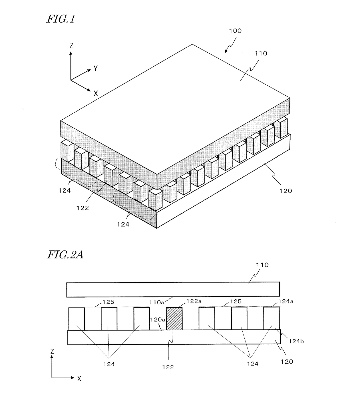
[0148]FIG. 12A is a perspective view schematically showing part of the structure of a waveguide device according to Embodiment 1 of the present disclosure. FIG. 12B is an upper plan view showing the waveguide device of FIG. 12A as viewed from the Z direction. FIG. 12A and FIG. 12B only show a portion close to a branching portion 136 of a waveguide member 122 in illustrative manners. In actuality, the conductive member 120, the waveguide member 122, and plural conductive rods 124 may also exist in the surroundings of the portion that is shown in the figure. This waveguide device further includes a conductive member 110 (see FIG. 1, etc.) covering over the waveguide member 122 and the plurality of conductive rods 124. The present embodiment differs in construction from the comparative example shown in FIG. 7 in that the waveguide member 122 has two recesses 137 in its side faces, near the branching portion 136.
[0149]Each of the second portion 122B and the third portion 122C of the wav...
embodiment 2
[0150]FIG. 13A is a perspective view schematically showing part of the structure of a waveguide device according to Embodiment 2 of the present disclosure. FIG. 13B is an upper plan view showing the waveguide device of FIG. 13A as viewed from the Z direction. In addition to the construction of Embodiment 1, impedance transformers are introduced in the first portion 122A of the waveguide member 122 according to the present embodiment. FIG. 13A and FIG. 13B only show a portion close to a branching portion 136 of a waveguide member 122 in illustrative manners. In actuality, the conductive member 120, the waveguide member 122, and plural conductive rods 124 may also exist in the surroundings of the portion that is shown in the figure. This waveguide device further includes a conductive member 110 (see FIG. 1, etc.) covering the waveguide member 122 and the plurality of conductive rods 124. The present embodiment differs in construction from the comparative example shown in FIG. 8A in th...
embodiment 3
[0161]FIG. 14A is a perspective view showing part of the structure of a waveguide device according to Embodiment 3 of the present disclosure. FIG. 14B is an upper plan view showing the structure of FIG. 14A as viewed from the Z direction. In the present embodiment, the impedance transformers 138A and 138B in the first portion 122A of the waveguide member 122 are realized by a structure with varying height, rather than width, of the waveguide face 122a. Moreover, on a side face opposite from the first portion 122A, the waveguide member 122 has a recess 139 at the junction (branching portion 136) where the first to third portions 122A to 122C are joined with one another, the recess 139 reaching the waveguide face 122a. In the present specification, the recess 137 in the second portion 122B of the waveguide member 122 may be referred to as a “first recess”, the recess 137 in the third portion 122C as a “second recess”, and the recess 139 in the branching portion 136 as a “third recess”...
PUM
 Abstract
Description
Claims
Application Information
 - R&D
- Intellectual Property
- Life Sciences
- Materials
- Tech Scout
- Unparalleled Data Quality
- Higher Quality Content
- 60% Fewer Hallucinations
Browse by: Latest US Patents, China's latest patents, Technical Efficacy Thesaurus, Application Domain, Technology Topic, Popular Technical Reports.
© 2025 PatSnap. All rights reserved.Legal|Privacy policy|Modern Slavery Act Transparency Statement|Sitemap|About US| Contact US: help@patsnap.com


