Surgical retractor

a retractor and surgical technology, applied in the field of surgical retractors, can solve the problems of many surgical retractors not taking into account, many surgical retractors not providing any advantages, and inconvenient use, so as to reduce cleaning costs, easy to maneuver and use, and reduce the risk of infection

Active Publication Date: 2018-10-09
INMOTUS MEDICAL LLC
View PDF31 Cites 27 Cited by
  • Summary
  • Abstract
  • Description
  • Claims
  • Application Information

AI Technical Summary

Benefits of technology

[0012]The present surgical retractor is ergonomically designed to make it easy to maneuver and use.
[0013]The surgical retractor is preferably, but not necessarily, for single use only. However, the surgical retractor may be made for multiple use. The surgical retractor may be, and preferably is, pre-sterilized and packed in a sterile packaging reducing set-up time, cleaning costs, and risk of infections. It may be used in both adult and pediatric patients.

Problems solved by technology

Many of these surgical retractors however, fail to provide any advantages such as, but not limited to, a less complicated and safer surgical procedure that can reduce the risk of nerve damage, anatomical deformity, and cross-contamination, reduce tension on the retracted site, and provide limited incision length.
Also, many surgical retractors do not take into account the anatomy of the surgical site and thus are not ergonomically designed.
If the surgical retractor is not designed and / or made for a specific procedure and / or tissue (e.g. tissue, muscle, muscles, or muscle groups), the risk of damage as noted above is greater.
However, the availability or amount of light at the surgical site is typically lacking.
Because heat is typically not desired during surgery, the surgical instruments and / or retractors use LEDs as the light source.
This restricts the ability to provide light to a targeted area during surgery, such as at or in the incision or incision area.
Therefore, it is easy to see that current surgical instruments / retractors restrict the visibility due to inadequate lighting within the working space.

Method used


Image

  • Surgical retractor
  • Surgical retractor
  • Surgical retractor

Examples


Embodiment Construction

[0028]Those of skill in the art will understand that various details of the invention may be changed without departing from the spirit and scope of the invention. Furthermore, the foregoing description is for illustration only, and not for the purpose of limitation.

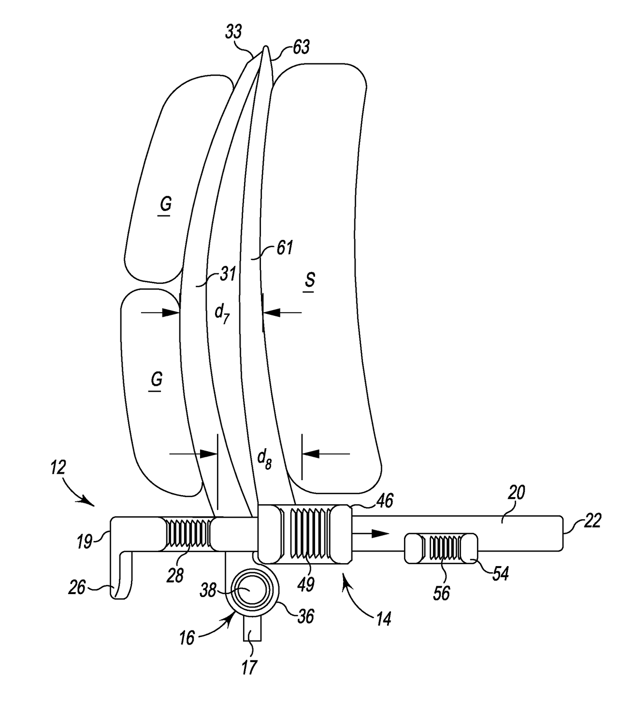
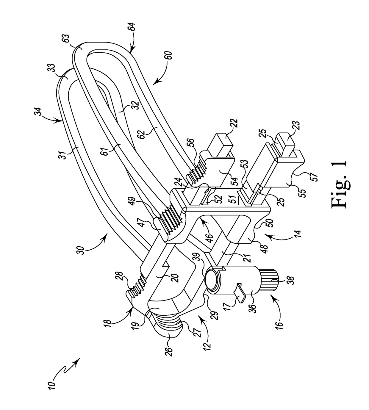
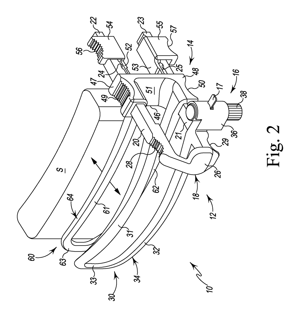
[0029]Referring to the Figures, there is shown a surgical retractor 10 for retracting tissue such as muscles during a surgical procedure. The surgical retractor 10 is preferably, but not necessarily, designed for one time use and thus in this form is disposable. In a multiple use form, the surgical retractor 10 may be made from a suitable metal, metal alloy, or other material that allows the surgical retractor 10 to be used multiple times and / or be cleaned and / or sterilized as necessary. The surgical retractor 10, with the exception of various components associated with light assembly 16 of the surgical retractor 10, is thus also preferably, but not necessarily, made from one or more appropriate plastics such as are known...


PUM


Abstract

A surgical retractor and method for retracting tissue in a patient is anatomically designed for particular muscles and includes a light source the light beam of which is positionable relative to the surgical retractor. The surgical retractor has a pair of retraction blades carried on separate retraction portions held open by ratchet assemblies. Blades are manually retracted and held open by automatically engaging ratchet fingers and are designed to match muscle curvature, minimizing various risks and incision size. The first retraction portion carries the first blade and includes tines each with ratchet grooves, while the second retraction portion carries the second blade on a carriage that is movably carried on the tines. Resilient spring actuated fingers associated with the carriage has ratchet grooves that co-act with the ratchet grooves of the tines to provide the ratchet assemblies between the retraction portions that regulates movement of the carriage and the second blade relative to the first blade.

Description

FIELD OF THE INVENTION[0001]The present disclosure relates to surgical retractors and devices for stabilizing tissue during a surgical procedure and, particularly, to surgical retractors for use in lower extremity, upper extremity, abdominal, rectal and other areas of the body during a surgical procedure.BACKGROUND[0002]Many surgical procedures necessitate the use of one or more surgical devices to retract tissue at the surgical site. Such surgical devices are generally known as surgical retractors. A wide variety of surgical retractors have been patented, some for general use and some for specific use. Many of these surgical retractors however, fail to provide any advantages such as, but not limited to, a less complicated and safer surgical procedure that can reduce the risk of nerve damage, anatomical deformity, and cross-contamination, reduce tension on the retracted site, and provide limited incision length.[0003]Also, many surgical retractors do not take into account the anatom...

Claims


Application Information

Patent Timeline
Patent Type & Authority Patents(United States)
IPC IPC(8): A61B17/02A61B90/30A61B17/00
CPCA61B17/0206A61B17/02A61B90/30A61B2090/309A61B2017/00424A61B2017/00734A61B2017/00407
Inventor PERLER, ADAM D.ZOELLNER, JAMES A.
Owner INMOTUS MEDICAL LLC
Why Eureka
Try Eureka