Installation for producing reinforcement cages for tower segments of wind turbines

a technology for wind turbines and cages, which is applied in the manufacture of final products, manufacturing tools, machines/engines, etc., can solve the problems that reinforcing cages cannot be handled with difficulty using conventional crane systems, and achieve the effect of efficient production of reinforcing cages

Inactive Publication Date: 2018-10-09
WOBBEN PROPERTIES GMBH
View PDF25 Cites 4 Cited by
  • Summary
  • Abstract
  • Description
  • Claims
  • Application Information

AI Technical Summary

Benefits of technology

[0011]One or more embodiments provide a system of the type described at the beginning which ensures efficient production of the reinforcing cages. In particular, the invention is also to be able to use said system in combination with, for example, the above-described known gripping device.
[0016]By using a first and a second handling robot, the number of manual work steps can be reduced, overall working safety is increased, and improved work planning is enabled. It has surprisingly proven to be the case that, despite the complex structure of the system and the many degrees of freedom during operation, it is possible to produce reinforcing cages in an efficient manner in terms of time.
[0018]In a preferred embodiment of the invention, the receiving area is arranged on a rotatable platform. The first and second handling robots are preferably arranged in a fixed location adjacent to the platform and / or can preferably be adjusted radially with respect to the center point of the platform. Because the handling robots are arranged adjacent to the preferably rotatable platform, an improved gain in space is obtained for the production site. Reinforcing cages for tower segments have a substantially cylindrical or frustoconical design so that rotation of the reinforcing cages on the receiving platform does not require any additional space in any direction.
[0021]Different types of stiffening elements can be formed in order to become part of the reinforcing cage. According to a first aspect, the stiffening elements are formed from a helically bent endless material. The stiffening elements are particularly preferably formed from a single helically bent steel wire that runs around the complete circumference of the ring elements. This structure is also called an upright helix. Such a design of the stiffening elements has the advantage that a bending and welding device for supplying the stiffening elements that is separate and hence has associated transport costs can be dispensed with.
[0027]According to a second aspect of the invention, the stiffening elements are designed as separate, preferably closed brackets. This design has the advantage that the arrangement of the individual stiffening elements around the ring elements can be handled in a more flexible manner and the handling process can be managed more simply. In the design according to this aspect of the invention, the stiffening elements are prefabricated in a separate production process and then held in stock in large quantities.

Problems solved by technology

A reinforcing cage has, for example, for the lowest, i.e., largest tower segment of a type E126 wind turbine from the ENERCON company, a diameter of approximately 14 m, a height of approximately 3.7 m and a weight of approximately 8.5 t. Because of its grid-like structure and the enormous dimensions, during manufacture reinforcing cages can only be handled with difficulty using conventional crane systems.

Method used


Image

  • Installation for producing reinforcement cages for tower segments of wind turbines
  • Installation for producing reinforcement cages for tower segments of wind turbines
  • Installation for producing reinforcement cages for tower segments of wind turbines

Examples


Embodiment Construction

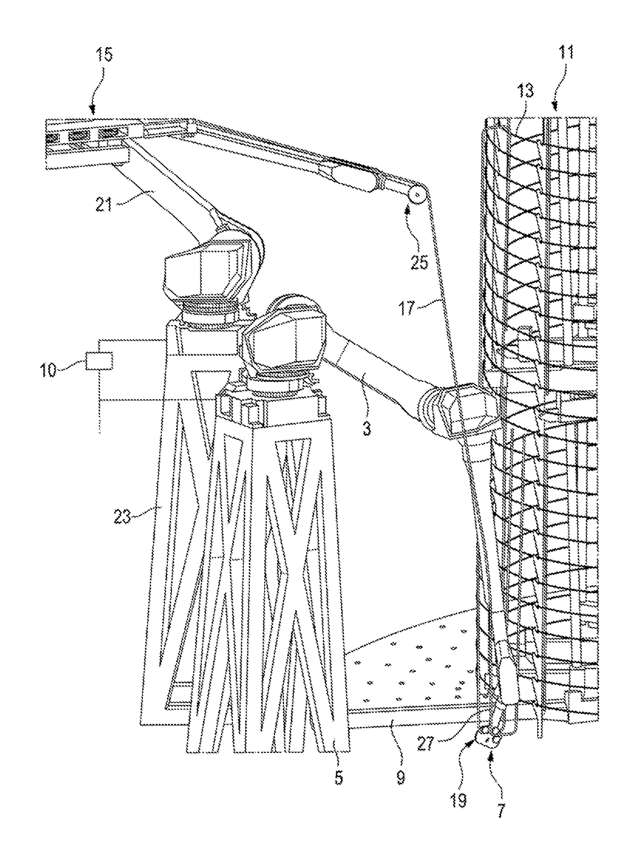
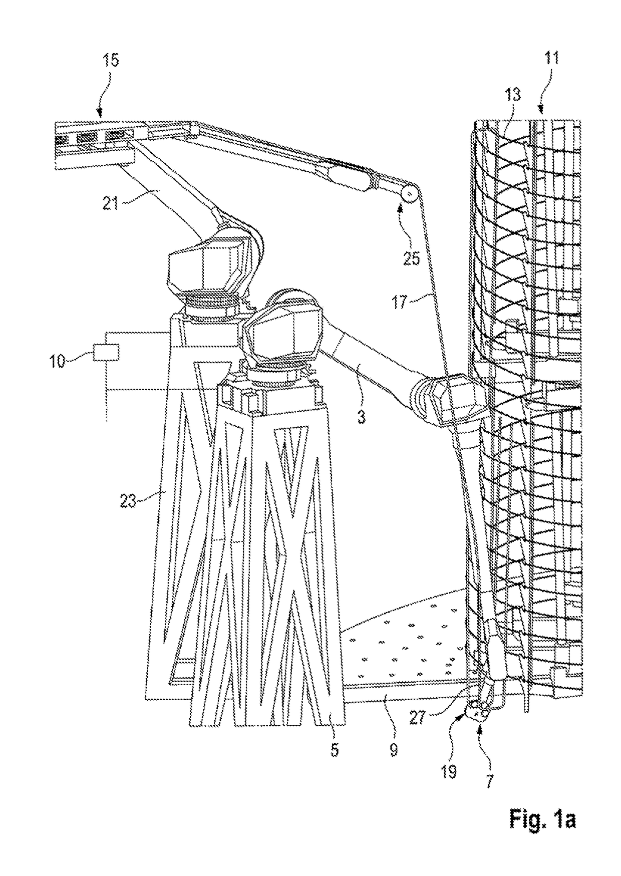
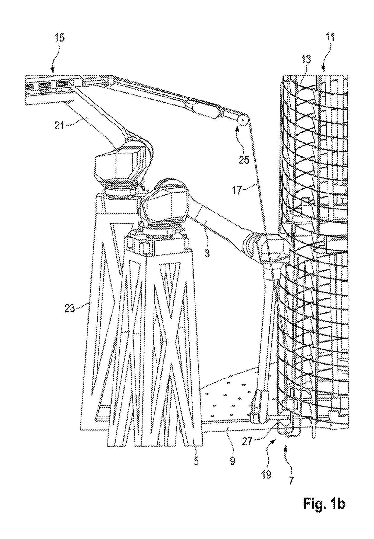
[0050]A system 1 according to a first exemplary embodiment of the invention is shown in FIG. 1a. The system 1 has a first handling robot 3 which is designed to form helically arranged stiffening elements 27 by means of corresponding bending means. The first handling robot 3 has a working head with a bending device 19. The first handling robot 3 is arranged in FIGS. 1a and 1b on a support structure 5. This can be a pedestal as in FIGS. 1a and 1b or another support structure, as shown for example in one of the other exemplary embodiments.

[0051]The system 1 has a receiving area 7. The receiving area 7 is configured so as to receive a gripping device 11. The gripping device 11 has coupling means, for example in the form of hook-shaped rake arms on which substantially horizontally oriented ring elements 13 are arranged in each case. The receiving area 7 is arranged on a preferably rotatable platform 9. The platform 9 is preferably connected to an electronic control unit by a data line so...


PUM

PropertyMeasurementUnit
weightaaaaaaaaaa
heightaaaaaaaaaa
heightaaaaaaaaaa

Abstract

A system for producing reinforcing cages for wind turbine tower segments, wherein a reinforcing cage has in each case substantially horizontally oriented ring segments and substantially vertically oriented stiffening elements. It is proposed that the system has a receiving area which is adapted so as to receive the preferably inner, substantially horizontally oriented ring segments of the reinforcing cage, a first handling robot for supplying and positioning the stiffening elements, and a second handling robot for connecting the ring elements to the stiffening elements.

Description

BACKGROUND[0001]Technical Field[0002]The present invention relates to a system for producing reinforcing cages for wind turbine tower segments, wherein a reinforcing cage has in each case substantially horizontally oriented ring segments and substantially vertically oriented stiffening elements.[0003]Description of the Related Art[0004]Towers such as those which are used, inter alia, for wind turbines often have a wall made from concrete or reinforced concrete. In particular in the case of dynamically loaded towers, which applies to the majority of towers owing to the effect of the wind, stiffening structures, so-called reinforcing cages, are additionally provided inside the tower wall in order to improve stability. A tower hereby has a segmental structure, i.e., a tower is composed of multiple superposed ring-shaped tower segments.[0005]In the production of such tower segments, the reinforcing cage is first produced and concrete is then poured into formwork provided for this purpos...

Claims


Application Information

Patent Timeline
Patent Type & Authority Patents(United States)
IPC IPC(8): B21F27/10B25J9/16F03D13/20B21F27/12B25J9/00E04C5/06E04H12/12B21F23/00F03D13/10E04H12/34B23K101/04B23K101/32
CPCE04C5/0609B21F27/10B21F27/124B21F27/125B25J9/1682B25J9/1687E04C5/0618E04H12/12F03D13/10F03D13/20B21F23/00B23K2101/32E04H12/341F05B2230/238F05B2230/61F05B2240/912Y02E10/728Y02P70/523Y10T29/49632Y10T29/5187B23K2101/04Y02P70/50
Inventor KRUGER, GEORGMEYER, INGOALBERS, KARSTEN
Owner WOBBEN PROPERTIES GMBH
Why Eureka
Try Eureka