System and method for diagnosing a variable displacement engine

a variable displacement, engine technology, applied in the direction of engines, machines/engines, electric control, etc., can solve the problems of increasing the possibility of degradation of one or more valve actuators that selectively activate and deactivate engine cylinders, increasing the difficulty of determining whether or not valve actuators are deactivating valves, and increasing the efficiency of cylinders that remain activated, so as to reduce engine pumping losses, improve thermal efficiency, and reduce the effect of engine pumping loss

Inactive Publication Date: 2018-10-09
FORD GLOBAL TECH LLC
View PDF3 Cites 8 Cited by
  • Summary
  • Abstract
  • Description
  • Claims
  • Application Information

AI Technical Summary

Benefits of technology

[0001]Cylinders of an engine may be selectively deactivated to conserve fuel while other cylinders continue to operate to propel a vehicle and to keep the engine rotating. The cylinders may be deactivated by holding intake and exhaust valves of deactivated cylinders in a closed state over an entire engine cycle (e.g., two revolutions for a four stroke engine). Efficiency of cylinders that remain activated increases by improving thermal efficiency and reducing engine pumping losses. Selected cylinders may be deactivated and reactivated responsive to driver demand torque and other vehicle operating conditions. For example, at low engine loads, an eight cylinder engine may combust air and fuel in four cylinders. On the other hand, the same eight cylinder engine may combust air and fuel in all eight cylinders during high driver demand conditions. In this way, the engine may enter and exit cylinder deactivation modes to accommodate different driving conditions.
[0004]By rotating an engine in a reverse direction and measuring engine air flow while the engine is rotating, it may be possible to provide the technical result of determining whether or not one or more cylinder valve actuator mechanisms is degraded. In particular, rotating an engine in a reverse direction while engine cylinders are not combusting air and fuel may provide an increased amount of air flow through the engine as compared to if the engine were rotated in a forward direction because of intake and exhaust valve timing. The increased air flow may provide an improved signal to noise ratio so that valve actuator diagnostics may be improved. Further, a higher air flow rate through the engine may allow the engine to be rotated at a lower speed while still being able to detect cylinder valve actuator degradation reliably.
[0005]The present description may provide several advantages. In particular, the approach may provide improved diagnostics of engine cylinder valve deactivation devices. Additionally, the approach may allow the engine to rotate at lower speeds when diagnostics are performed so that the diagnostics may be less noticeable. Further, the approach may conserve battery power by performing diagnostics at lower engine speeds when the engine is not combusting air and fuel and is rotated via an electric machine.

Problems solved by technology

On the other hand, the same eight cylinder engine may combust air and fuel in all eight cylinders during high driver demand conditions.
Over time and varying vehicle operating conditions, the possibility of degradation of one or more valve actuators that selectively activate and deactivate engine cylinders may increase.
However, it may be difficult to determine whether or not valve actuators are deactivating valves as desired while the engine is operating without disturbing passengers of a vehicle that includes the engine.
Further, a signal to noise ratio for determining cylinder valve actuator degradation may be low while the engine is operating because exhaust gas recirculation (EGR), barometric pressure, and other engine operating conditions may affect the signal to noise ratio of signals used to determine valve actuator degradation.

Method used


Image

  • System and method for diagnosing a variable displacement engine
  • System and method for diagnosing a variable displacement engine
  • System and method for diagnosing a variable displacement engine

Examples


Embodiment Construction

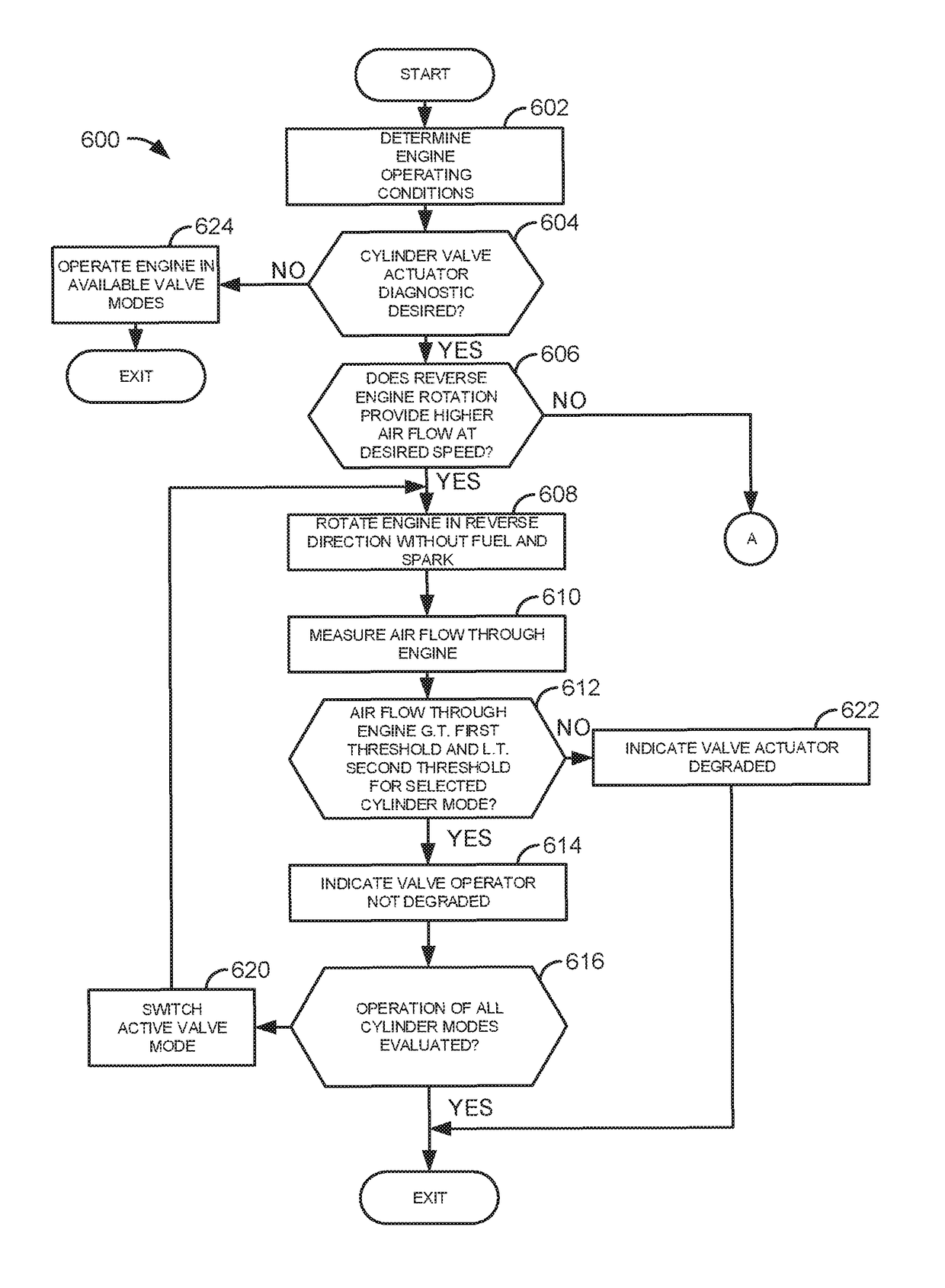
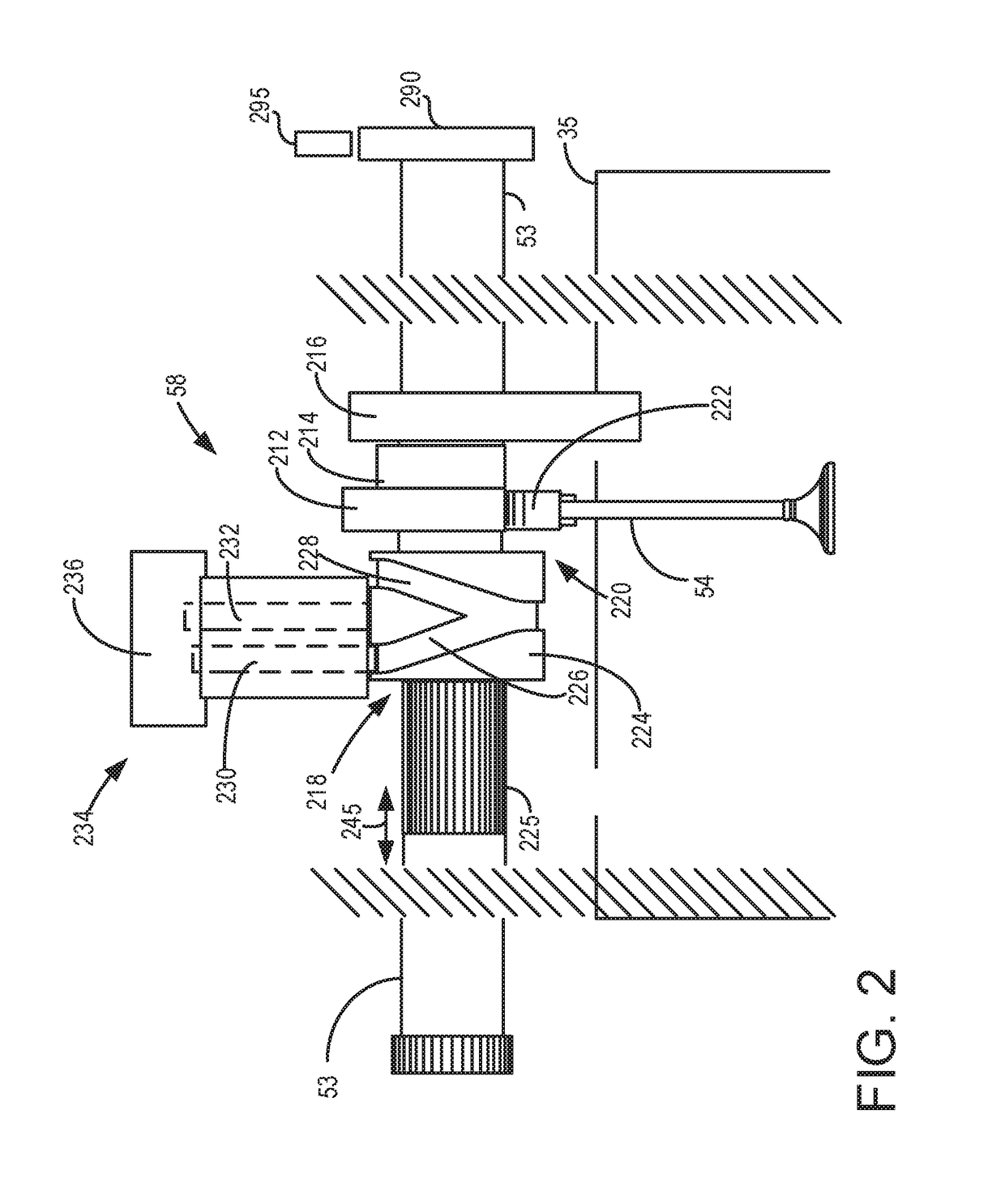
[0013]The present description is related to providing diagnosing operation of an engine that includes actuating mechanisms for cylinder valves. The actuating mechanisms may be included in the engine to selectively deactivate intake and exhaust valves of engine cylinders to activate and deactivate engine cylinder modes. An example actuating mechanism for cylinder valves is shown in FIG. 2. Example valve timings are shown in FIGS. 3A-3B while example engine cylinder configurations are shown in FIGS. 4A and 4B. A sequence for determining the presence or absence of valve actuator degradation is shown in FIG. 5. The method of FIGS. 6A and 6B diagnoses the presence or absence of valve actuator degradation.

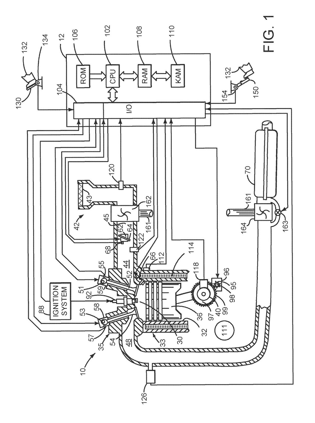
[0014]Referring to FIG. 1, internal combustion engine 10, comprising a plurality of cylinders, one cylinder of which is shown in FIG. 1, is controlled by electronic engine controller 12. Engine 10 is comprised of cylinder head 35 and block 33, which include combustion chamber 30 and cyli...


PUM


Abstract

Systems and methods for determining operation of a cylinder deactivating / reactivating device are disclosed. In one example, a direction of engine rotation is selected to maximize air flow through the engine while the engine is rotated without combusting air and fuel. Operation of one or more cylinder valve deactivating mechanisms is assessed while the engine is rotated without combusting air and fuel.

Description

BACKGROUND AND SUMMARY[0001]Cylinders of an engine may be selectively deactivated to conserve fuel while other cylinders continue to operate to propel a vehicle and to keep the engine rotating. The cylinders may be deactivated by holding intake and exhaust valves of deactivated cylinders in a closed state over an entire engine cycle (e.g., two revolutions for a four stroke engine). Efficiency of cylinders that remain activated increases by improving thermal efficiency and reducing engine pumping losses. Selected cylinders may be deactivated and reactivated responsive to driver demand torque and other vehicle operating conditions. For example, at low engine loads, an eight cylinder engine may combust air and fuel in four cylinders. On the other hand, the same eight cylinder engine may combust air and fuel in all eight cylinders during high driver demand conditions. In this way, the engine may enter and exit cylinder deactivation modes to accommodate different driving conditions.[0002...

Claims


Application Information

Patent Timeline
Patent Type & Authority Patents(United States)
IPC IPC(8): F02D17/02F02N11/08F02D13/02F02D41/00
CPCF02D17/02F02N11/0818F02D13/0203F02D41/0087F02D41/221F02D41/18F02D2250/06F02N11/04Y02T10/12Y02T10/40
Inventor DUDAR, AED M.
Owner FORD GLOBAL TECH LLC
Why Eureka
Try Eureka