Sealed battery and a method for manufacturing the same

a technology of sealed batteries and sealing parts, which is applied in the direction of batteries, sustainable manufacturing/processing, cell components, etc., can solve the problems of insufficient weld strength at the boundary between the case main body and the sealing member, foreign matter (typically metallic particles) from spatter may end up in the battery case, and achieve the effect of sufficient fracture strength

Active Publication Date: 2018-10-16
TOYOTA JIDOSHA KK
View PDF21 Cites 1 Cited by
  • Summary
  • Abstract
  • Description
  • Claims
  • Application Information

AI Technical Summary

Benefits of technology

[0012]The invention thus provides a sealed battery in which joint strength of a boundary between a case main body and a sealing member is stably ensured, and in which fracturing at a boundary portion of a weld portion and a non-weld portion of a welding member is reduced.
[0016]According to this aspect, by making the weld portion have the weld bottom portion, the length in the weld depth direction along the boundary surface of the weld portion, on the plane that includes the boundary surface of the a member, from among the case main body and the sealing plate, in which a direction along the boundary surface corresponds to a thickness direction thereof (hereinafter, referred to as first member) and the second member, (i.e., the length D) is able to be stably ensured. For example, even if there is variation in the battery manufacturing process (e.g., variation in the welding position, variation in the sizes of the case and the sealing plate, etc.), a desired length is able to be stably ensured for the length of the weld portion in the weld depth direction along the boundary surface, on the plane that includes the boundary surface of the first member and the second member. That is, the strength of the weld portion is able to be stably ensured on the plane that includes the boundary surface of the case main body and the sealing plate. Also, because the weld portion extends to the outer surface of the second member that is the outer surface on the opposite side in the thickness direction from the boundary surface between the first member and the second member, and d≤0.7×D is satisfied, the area of the boundary between the weld portion and the non-weld portion of the second member is increased. That is, fracturing at the boundary portion of the weld portion and the non-weld portion of the second member is able to be reduced.
[0018]According to this aspect, the area of the boundary between the weld portion and the non-weld portion of the second member is able to be sufficiently ensured. Therefore, even if a thin second member is used, fracturing at the boundary portion of the weld portion and the non-weld portion of the second member is able to be reduced.
[0022]Typically, the thickness of the sealing plate is set larger than the thickness of the case main body. Therefore, by having the first member be the sealing plate, a sufficient length of the weld portion to ensure the strength (fracture strength) of the weld portion on the plane that includes the boundary surface of the case main body and the sealing plate is able to be relatively easily ensured for the length of the weld portion in the weld depth direction along the boundary surface, on the plane that includes the boundary surface of the case main body and the sealing plate (i.e., the length D). Also, with the sealed battery of the aspect of the invention, fracturing at the boundary portion of the weld portion and the non-weld portion of the case main body that is the second member is able to be reduced. That is, with the sealed battery of the above aspect, it is possible to provide a sealed battery in which sufficient fracture strength is ensured at a portion where the case main body and the sealing plate are joined together by welding.
[0024]According to this second aspect, by using a suitable combination of three or more mutually independent laser beams and appropriately irradiating these laser beams at the sealing plate and the case main body that are the welding members, the shape of a portion melted by the laser beams (i.e., the weld portion where the melted portion has solidified) is able to be controlled to a desired shape. As a result, a sealed battery in which the strength of the weld portion on the plane that includes the boundary surface of the case main body and the sealing plate is ensured, and fracturing at the boundary portion of the weld portion and the non-weld portion of the welding members is reduced, is able to be manufactured. That is, a sealed battery in which sufficient fracture strength is ensured for a portion where the case main body and the sealing plate are joined together by welding is able to be provided.

Problems solved by technology

However, with the technology described in JP 11-104866 A, if the welding position (typically a laser irradiating position) is off, a desired weld depth may not be able to be ensured at the weld portion of the butt portion of the case main body and the sealing member (i.e., the boundary between the case main body and the sealing member).
That is, weld strength at the boundary between the case main body and the sealing member may not be able to be sufficiently ensured due to variation in the battery manufacturing process (e.g., variation in the welding position, variation in the sizes of the case and sealing member, etc.).
Also, if the weld depth of the weld portion is excessive and the location that has melted at the time of welding (i.e., the melted portion) ends up reaching (ends up passing through) the inside wall of the battery case, foreign matter (typically metallic particles) from spatter may end up getting into the battery case at the time of welding.
Foreign matter (spatter) that gets into the battery case may cause an internal short in the battery, and is thus undesirable.
This void (cavity) reduces the strength of the weld location (weld strength), which leads to a decrease in weld quality and is therefore undesirable.
Therefore, with the technology described in JP 2009-218099 A, even though the joint strength of the boundary (butt portion) of the case main body and the sealing member is able to be increased, there are cases in which it is difficult to ensure sufficient weld strength at the boundary portion of the non-weld portion and the weld portion of the case main body.

Method used


Image

  • Sealed battery and a method for manufacturing the same
  • Sealed battery and a method for manufacturing the same
  • Sealed battery and a method for manufacturing the same

Examples


Embodiment Construction

[0039]Hereinafter, example embodiments of the invention will be described with reference to the accompanying drawings as appropriate. In this specification, matter that is not particularly mentioned, that is necessary to carry out the invention may be understood to be design matter of one skilled in the art based on the related art in this field. The invention may be carried out based on technical common knowledge in the field and the content described in this specification. In the drawings described below, like reference characters will be used to denote members and portions that perform the same operation. Also, dimensional relationships (length, width, thickness and the like) in the drawings do not reflect the actual dimensional relationships.

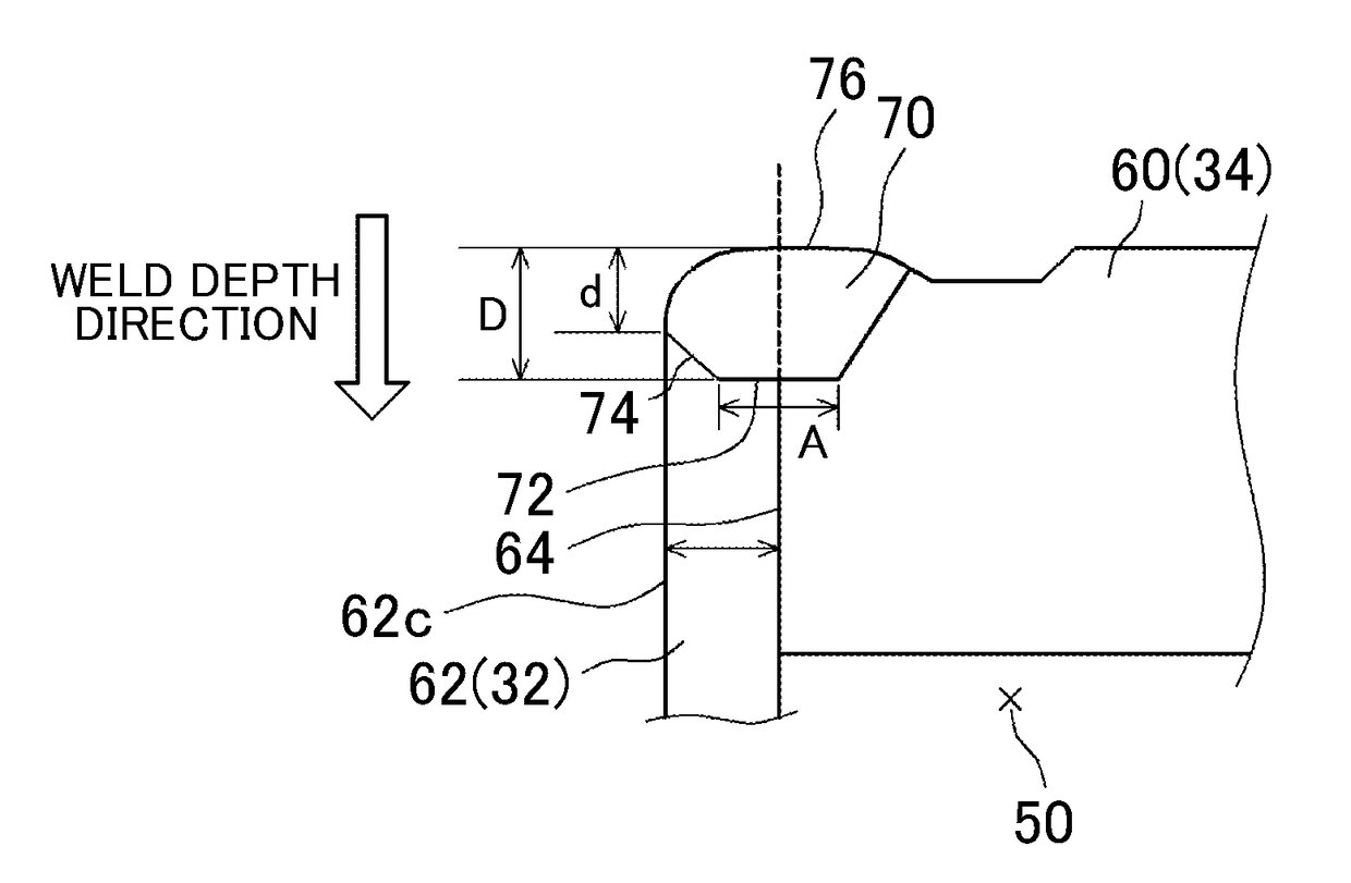
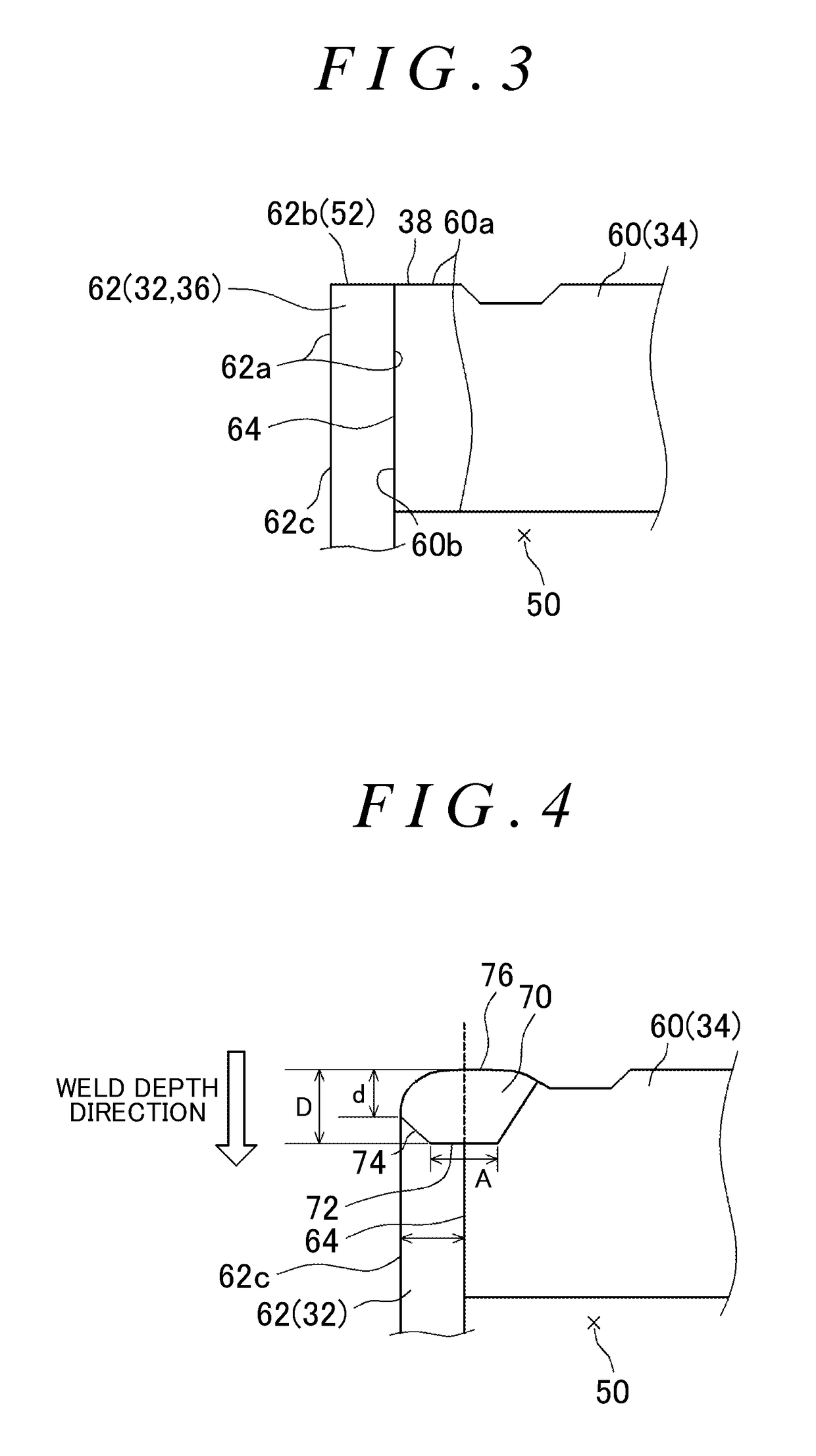
[0040]The battery of according to an example embodiment of the invention is a sealed battery in which a sealing plate and a case main body of a battery case are joined together by welding, as described above, and is characterized by the shap...


PUM

PropertyMeasurementUnit
thicknessaaaaaaaaaa
distanceaaaaaaaaaa
thicknessaaaaaaaaaa

Abstract

A sealed battery includes: a case main body that has an opening; and a sealing plate that closes off the opening, the sealing plate being joined to the case main body by a weld portion. The weld portion includes a weld bottom surface intersecting with the boundary surface of the case main body and the sealing plane, and the weld bottom surface being substantially orthogonal to the depth direction. A depth of the weld portion on a first virtual plane including the boundary surface, is greater than the depth of the weld portion on a second virtual plane including an outer surface of the case main body, the outer surface being opposite side from the boundary surface in the thickness direction of the case main body.

Description

INCORPORATION BY REFERENCE[0001]The disclosure of Japanese Patent Application No. 2015-119095 filed on Jun. 12, 2015 including the specification, drawings and abstract is incorporated herein by reference in its entirety.BACKGROUND OF THE INVENTION[0002]1. Field of the Invention[0003]The invention relates to a sealed battery and a method for manufacturing the same.[0004]2. Description of Related Art[0005]One representative structure of a battery is a structure in which a power generating element formed by a positive electrode and a negative electrode stacked together with a separator in between is housed in a battery case, and this battery case is sealed (i.e., a sealed battery). Typically with this sealed battery, the inside of the battery case is sealed by closing off (sealing) an opening of the case main body with a suitable sealing member (for example, a sealing plate) after the power generating element is housed in a case main body. One method for sealing the opening of this bat...

Claims


Application Information

Patent Timeline
Patent Type & Authority Patents(United States)
IPC IPC(8): H01M2/04H01M2/02H01M50/103H01M50/148H01M50/169H01M50/191
CPCH01M2/0469H01M2/0237H01M2/043H01M2/0439H01M2/0473H01M2/0426H01M2220/20H01M50/191H01M50/103H01M50/148H01M50/169Y02E60/10H01M50/15Y02P70/50H01M10/058H01M50/10
Inventor UMEYAMA, HIROYAHARIMA, YUKIO
Owner TOYOTA JIDOSHA KK
Why Eureka
Try Eureka