Adjustable size inlet system

a technology of inlet lip and adjustable size, which is applied in the direction of mechanical equipment, machines/engines, transportation and packaging, etc., can solve the problems of reducing the performance of aircraft, the design of inflatable inlet lip is vulnerable to rapid aging, and the inlet lip is not providing the favorable pressure profile needed for efficient thrust production at low flight speed

Active Publication Date: 2018-10-23
THOMAS INT
View PDF61 Cites 13 Cited by
  • Summary
  • Abstract
  • Description
  • Claims
  • Application Information

AI Technical Summary

Benefits of technology

[0013]The adjustable size inlet system may further include a plurality of sidewall extenders within the nacelle, each sidewall extender shortening and elongating to adjust a length of a sidewall within the nacelle formed by each sidewall extender, thereby accommodating the expansion and contraction of the plurality of interleaved petals.
[0016]The adjustable size inlet system may further include a plurality of equipment bays. Each equipment bay may include an upper equipment bay formed within the nacelle and sealed at one end by one of the plurality of equipment bay doors. The one equipment bay door may be raised and lowered by the sliding door operating assembly. The one equipment bay door may be lowered to prevent mechanical interference with the petal array when the circumference of the adjustable size inlet lip is increased. The one equipment bay door may be raised to maintain the seal at the one end of the equipment bay when the circumference of the adjustable size inlet lip is decreased. Each equipment bay door may be guided by an embedded linear guidebar operatively coupled to an extension track affixed over the one end of the equipment bay to transition from the raised position to a lowered position. The equipment bay doors may be lowered and raised to provide space in the equipment bay for the expanded bellmouth for the adjustable size inlet when in vertical lift mode
[0028]In an additional aspect, a ducted fan propulsion system is provided that includes a main fan duct and an adjustable size inlet attached at an end of the main fan duct. The adjustable size inlet may include: a plurality of nested structural tubes operatively coupled in a sliding arrangement and forming a ring; a petal array comprising an interleaved plurality of petals arranged around a perimeter of the ring to define an adjustable size inlet system; and a plurality of actuators to cause the plurality of nested structural tubes to move radially outward and inward, thereby causing an increase or a decrease of a circumference of the adjustable size inlet lip. Each petal may include: an upper portion curved over, and at least partially enclosing, a first portion of the plurality of nested structural tubes; and a lower portion attached to the main fan duct.
[0036]In yet another aspect, a nacelle is provided that includes: a fan duct extending between a duct inlet and a duct exit; a plurality of interleaved petals arranged around a perimeter of the duct inlet; a plurality of actuators to expand the plurality of interleaved petals to form a bellmouth inlet profile and to contract the plurality of interleaved petals to form a cylindrical inlet profile; a plurality of control rods arranged around a perimeter of the fan duct to limit expansion of the plurality of interleaved petals; a plurality of sliding doors arranged around an outer perimeter of the nacelle adjacent to the plurality of interleaved petals, the plurality of sliding doors sliding to remain adjacent to the plurality of interleaved petals throughout the expansion and contraction of the plurality of interleaved petals; and a plurality of sidewall extenders within the nacelle to shorten and elongate, each sidewall extender shortening and elongating to adjust a length of a sidewall within the nacelle formed by each sidewall extender, thereby accommodating the expansion and contraction of the plurality of interleaved petals.

Problems solved by technology

This bellmouth profile, characterized by a relatively rounded inlet lip, may produce detrimental profile drag at high flight speeds, thereby reducing the aircraft's performance.
To enhance high speed performance, a sharper inlet lip may be provided in place of the rounded inlet lip, but the sharper inlet lip fails to provide the favorable pressure profile needed for efficient thrust production at low flight speeds.
However, this inflatable inlet lip design may be vulnerable to rapid aging and to sudden failure with associated foreign object damage to the engine.

Method used


Image

  • Adjustable size inlet system
  • Adjustable size inlet system
  • Adjustable size inlet system

Examples


Embodiment Construction

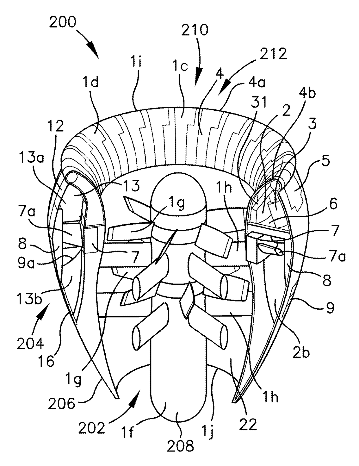
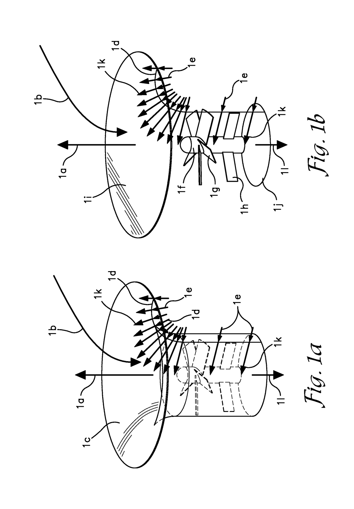
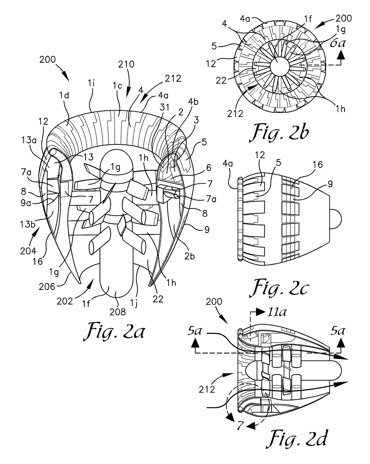
[0105]In various aspect of the disclosure, an adjustable size ducted fan system is provided that includes a main fan assembly and an exterior bypass fan assembly housed within a nacelle. The main fan assembly may include a multi-stage counter-rotating fan housed within an adjustable size fan duct. The adjustable size fan duct provides the capability to vary the contour of the inlet duct to enhance thrust production over a variety of conditions including, but not limited to, hovering flight, low speed forward flight, and high speed forward flight. The exterior bypass fan assembly may include a toroidal fan attached to the outer perimeter of the main fan duct. The inlet airflow to the toroidal fan may be provided by a plurality of exterior bypass ducts within an outer portion of the nacelle that may be opened and closed to produce additional thrust as needed for a variety of conditions including, but not limited to takeoff, landing, and high speed forward flight.

[0106]The nacelle cont...


PUM


Abstract

An adjustable size inlet duct system for a ducted fan propulsion system may change its inlet profile to enhance thrust levels in low-speed and hovering flight conditions and may change its inlet profile to reduce drag to permit faster flight speeds at higher operating speeds. The adjustable size inlet duct system may include duct petals and associated actuators. During slow speed flight, the petals may expand to generate a rounded large inlet area bellmouth profile. At higher flight speeds, the petals may contract to reduce the profile drag of the duct in forward flight. An optional exterior bypass duct may be included to provide additional thrust in excess of the thrust provided by the ducted fan. An optional annular electric motor housed in the exterior bypass duct may be included to generate still more excess thrust.

Description

FIELD OF THE DISCLOSURE[0001]The present disclosure relates to a new class of aircraft ducted fan devices that are capable of changing their inlet profile in response to their flight condition. The variable-shape duct inlets can be more closely optimized for a variety of conditions including hovering flight, low speed flight, and high speed flight conditions.BACKGROUND[0002]A wide variety of aircraft ducted fan systems have been experimented with for many years. A typical ducted fan system may include an inlet duct to direct an inflow of air to a rotating set of impellors situated downstream of an inlet face. The inlet duct may be contoured into a bellmouth profile that induces an internal duct pressure profile that is favorable for efficient thrust production at low speeds. This bellmouth profile, characterized by a relatively rounded inlet lip, may produce detrimental profile drag at high flight speeds, thereby reducing the aircraft's performance. To enhance high speed performance...

Claims


Application Information

Patent Timeline
Patent Type & Authority Patents(United States)
IPC IPC(8): F02K3/077F02C7/042B64D33/02F02K3/06
CPCF02C7/042B64D33/02F02K3/06F02K3/077B64D2033/0286B64D2033/0226B64D2033/0253F02C3/107
Inventor DEVINE, MICHAEL THOMAS
Owner THOMAS INT
Why Eureka
Try Eureka