
Ground fault circuit interrupter and reset mechanism thereof

Active Publication Date: 2018-10-30
JIANGSU BAREP INTELLIGENCE TECH CO LTD
View PDF37 Cites 1 Cited by
  • Summary
  • Abstract
  • Description
  • Claims
  • Application Information

AI Technical Summary

Benefits of technology

The invention provides a reset mechanism for a GFCI that is easy to assemble and has a simple design. The use of a tact switch composed of a stationary and a moving contact switch reed reduces production costs even further. This simplifies the assembly process and reduces production costs.

Problems solved by technology

In a practical production process, assembling is hard to implement, greatly affecting assembly efficiency and increasing production costs.

Method used


Image

  • Ground fault circuit interrupter and reset mechanism thereof
  • Ground fault circuit interrupter and reset mechanism thereof
  • Ground fault circuit interrupter and reset mechanism thereof

Examples


Embodiment Construction

[0016]Specific implementations of a GFCI according to the present invention are described below in detail with reference to the accompanying drawings.

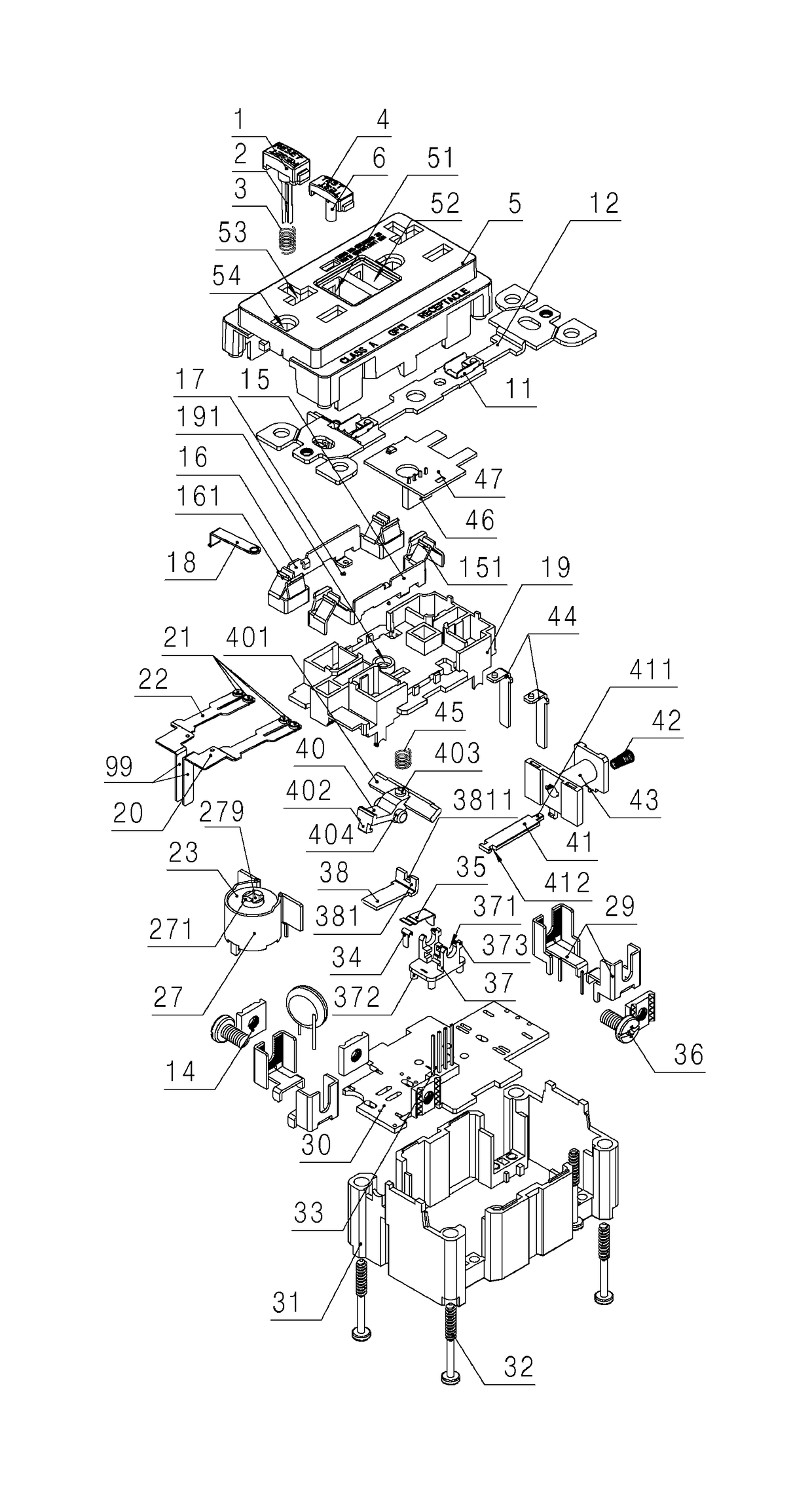
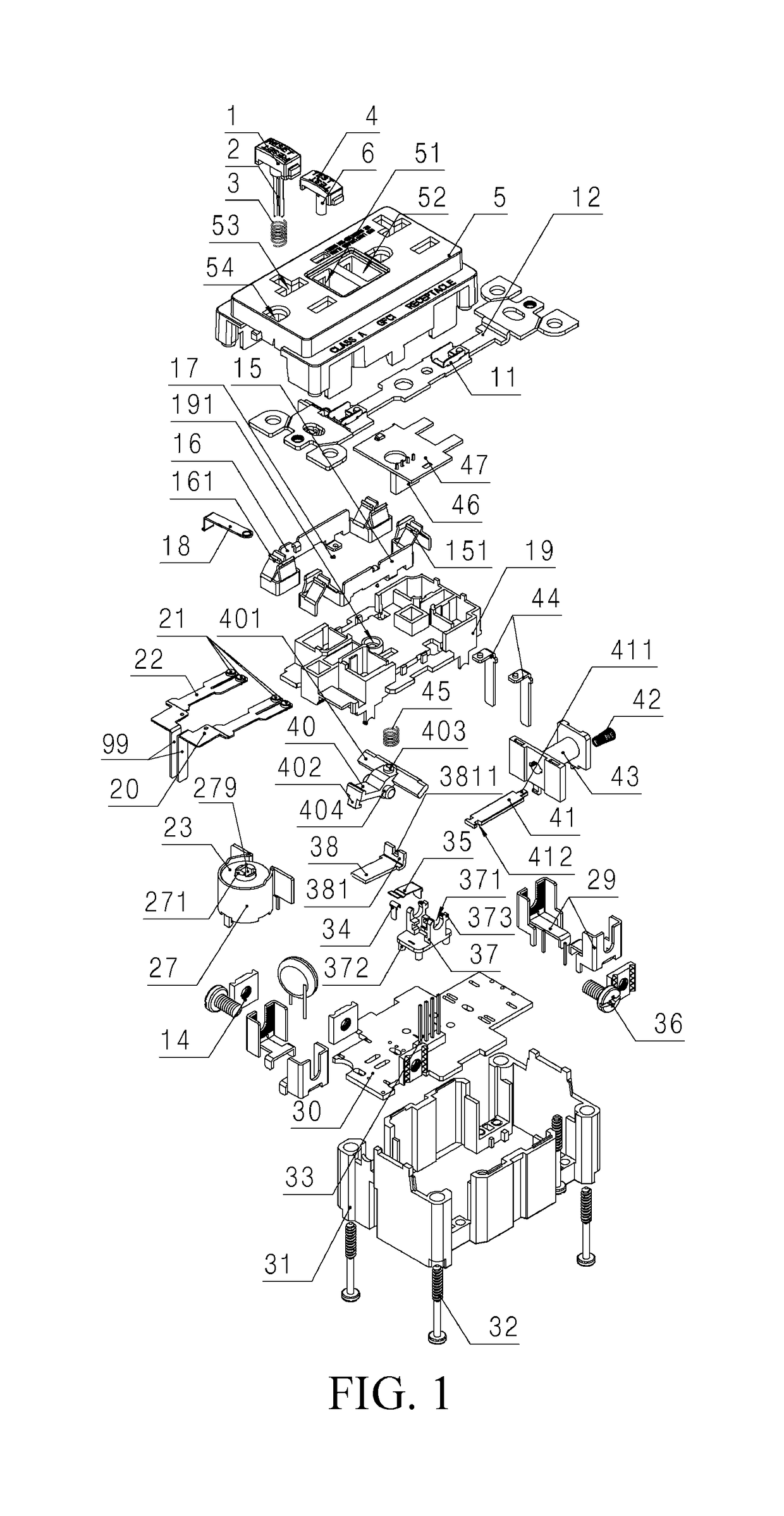
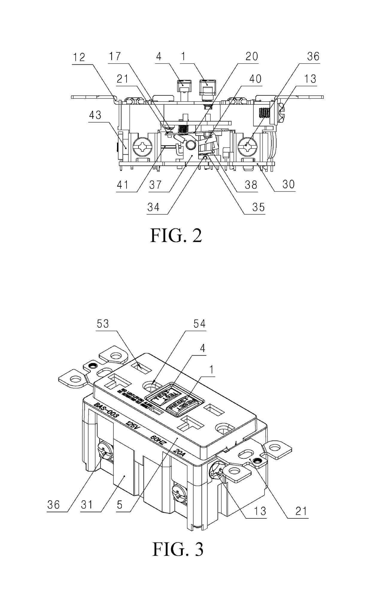
[0017]As shown in FIG. 1 and FIG. 3, a structure of a GFCI according to the present invention includes: an enclosure composed of a plastic bottom case 31 and an upper cover 5. The enclosure is provided with a primary circuit board 30, a second input end connecting plate 20, a first input end connecting plate 22, a pair of input terminals 29, a ground bracket 12, a mounting middle frame 19, a test button 4, a reset mechanism, and a tact switch composed of a stationary contact switch reed 34 and a moving contact switch reed 35. As shown in FIG. 2, the reset mechanism includes: a reset button 1, an electromagnet, a slide rocker 38, a rotary lifting block 40, and a plastic reset mounting bracket 37 mounted on the primary circuit board 30. A specific mounting manner of the reset mounting bracket 37 is that: four positioning rods 371 are dis...


PUM


Abstract

A reset mechanism includes: a reset button, electromagnet, and reset mounting bracket, where a rotary lifting block is movably on the bracket; lifting parts are separately at two sides of one end of the block, and a clamping hook is the other end; a lifting block spring is on one side of the lifting part of the block; a position-limiting block matched with the block is on the bracket, which has a slide rocker in a movable manner; a rocker bending part is at a tail of the slide rocker; an end part of the rocker bending part has a rocker bayonet; an iron core of the electromagnet has an iron core card slot matched with the bayonet, which is clamped to the iron core card slot; and a bottom of the reset button has a reset lever matched with one side of the clamping hook of the block.

Description

BACKGROUNDTechnical Field[0001]The present invention relates to a power socket, and in particular, to a ground fault circuit interrupter (GFCI for short in English).Related Art[0002]As is known to all, a reset mechanism of a current GFCI is relatively complex, and a structure thereof usually includes: a lock mounting bracket mounted on a primary circuit board, a lifting chute surrounded by four columns and disposed in the lock mounting bracket, a lifting slider disposed in the lifting chute in a movable manner, a reset lever hole through from top to bottom disposed in the lifting slider, an upper reset spring hole located on an upper bead of the reset lever hole, and a lower reset spring hole located on a lower bead of the reset lever hole, where a top of the lower reset spring is inserted into the lower reset spring hole; a bottom of the lower reset spring abuts against the lock mounting bracket; a bottom of the upper reset spring is inserted into the upper reset spring hole; a top...

Claims


Application Information

Patent Timeline
IPC IPC(8): H01H73/00H01H71/58H01H71/02H01H71/68
CPCH01H71/58H01H71/0207H01H71/68H01H2235/01H01H83/02H01H2071/665H01H71/2445
Inventor CHEN, JIANGANGYIN, ZHENJUN
Owner JIANGSU BAREP INTELLIGENCE TECH CO LTD
Learn More